



Replacing an old conveyor idler is straightforward when the original drawing, part number, or equipment specification is still available. The situation becomes more difficult when the conveyor has been operating for many years, the original supplier can no longer be contacted, or the idler has been modified during previous maintenance.
In these cases, the safest approach is not to order a replacement by belt width or roller diameter alone. The old roller or complete idler assembly should be measured systematically so the new component matches the existing conveyor frame, belt profile, mounting points, and operating position.
For most replacement projects, the most important dimensions include roller diameter, roller body length, overall shaft length, shaft-end dimensions, mounting-center distance, trough angle, frame dimensions, and installation-hole positions. The exact measurements required depend on whether the customer is replacing one roller or the entire idler set.
Quick answer: If an old conveyor idler has no drawing, first identify whether you need an individual roller or a complete idler assembly. For a roller, measure the shell diameter, shell length, overall shaft length, shaft-end shape and dimensions, and mounting distance. For a complete idler set, also measure the frame width, mounting-hole centers, roller arrangement, trough angle, and installation height. Add clear photos from the front, side, and shaft ends before requesting a quotation.
First Determine What Actually Needs to Be Replaced
Before taking dimensions, confirm whether the failed component is a single conveyor roller or a complete idler assembly.
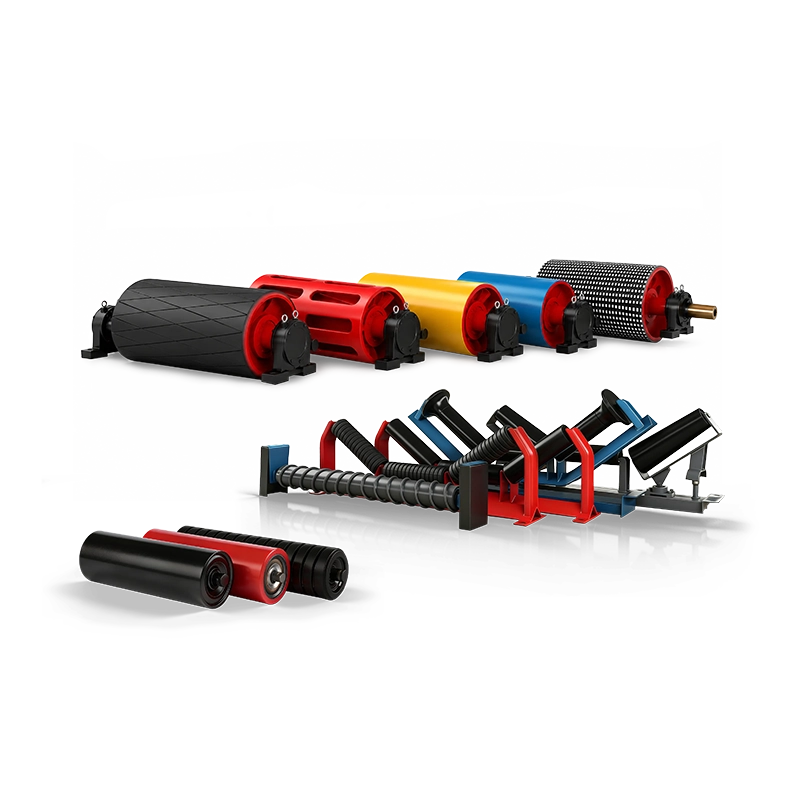
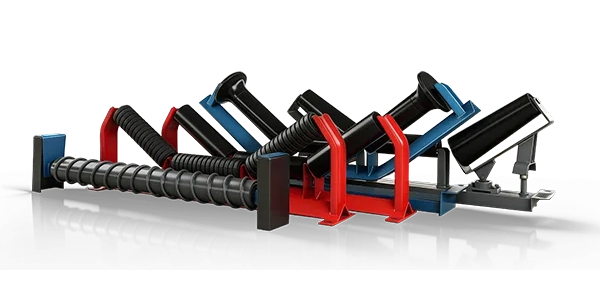
A roller is the cylindrical rotating component that contacts and supports the conveyor belt. An idler normally refers to the complete support assembly, which may include one, two, or three rollers together with brackets or a supporting frame.
This distinction is important because a replacement roller may require only a few critical dimensions, while replacing an entire troughing or return idler requires considerably more information about the frame and belt geometry.
For a detailed explanation of the main carrying, return, impact, transition, and training arrangements, see the Conveyor Idler Types and Applications Guide.
What Tools Should Be Used for Measuring an Old Idler?
A complicated inspection system is usually unnecessary. Most replacement dimensions can be collected with common maintenance tools, provided measurements are taken carefully.
Recommended tools:
steel tape measure for longer dimensions;
vernier caliper for shaft and shell dimensions;
angle gauge or digital inclinometer for trough angle;
straightedge for checking mounting positions;
marker and notebook for identifying dimensions;
mobile phone or camera for detailed reference photos.
Whenever possible, remove one representative roller from the conveyor before measuring it. Shaft ends and hidden installation dimensions are often difficult to measure accurately while the roller remains inside the frame.
1. Measure the Roller Shell Diameter
The roller outside diameter is one of the first dimensions suppliers need. Measure the steel tube or roller body itself rather than estimating diameter from the bearing housing or seal area.
Use a caliper where practical and take measurements at several locations around the roller. Old rollers may be worn, corroded, dented, or covered with material buildup, so one measurement may not represent the original size.
Important: Do not automatically use the smallest diameter measured on a heavily worn roller as the replacement diameter. Compare an unworn area near the end of the shell or measure another roller from the same idler set before confirming the dimension.
2. Measure the Roller Body Length
The roller body length is the usable cylindrical shell length between the two ends of the roller body. This is different from the overall shaft length.
For a three-roll troughing idler, measure the center roller and wing rollers separately. Do not assume all three rollers have the same face length unless the actual assembly confirms it.
For impact rollers, measure the total effective roller face as well as the arrangement of rubber rings if an exact replacement is required. For rubber-disc or spiral return rollers, record the overall working length and the special surface arrangement.
3. Measure the Overall Shaft Length
One of the most common replacement mistakes is supplying only the roller shell length and ignoring the shaft.
Measure from the extreme end of the shaft on one side to the extreme end on the other side. This is the overall shaft length.
The replacement roller must fit between the existing mounting brackets. Even if two rollers have identical shell diameter and shell length, different shaft lengths can make them incompatible with the frame.
4. Measure the Shaft Diameter and Shaft-End Shape
Shaft-end geometry is one of the most important dimensions when reverse-engineering an old conveyor roller.
Depending on the idler design, the shaft end may be round, machined flat on two sides, slotted, threaded, stepped, drilled, or designed for a specific bracket connection.
Measure the main shaft diameter and then separately measure the mounting section at each end.
| Shaft Measurement | What to Record |
| Main Shaft Diameter | Diameter of the main shaft section |
| End Length | Length extending beyond roller body |
| Across Flats | Distance between machined flat surfaces where applicable |
| Slot or Groove | Width, depth, length, and position |
| Thread | Thread diameter and usable threaded length where applicable |
Take close-up photographs of both shaft ends beside a ruler or caliper. A photo often reveals a mounting detail that may be missed in a written measurement list.
5. Measure the Effective Mounting Distance
Overall shaft length alone may not define how the roller sits in the existing frame. The supplier also needs to understand where the shaft actually contacts or locks into the mounting brackets.
Measure the distance between the two effective mounting points or between the inside faces of the supporting brackets. If the shaft has flats, slots, locating shoulders, or grooves, record their positions relative to the roller body.
This measurement is especially important when replacing rollers on older conveyors where the original frame follows a manufacturer-specific mounting arrangement.
6. Measure the Existing Idler Frame When Replacing the Complete Set
If the entire troughing, impact, return, or training idler is being replaced, roller measurements alone are not enough.
The new frame must match the conveyor stringer and maintain the existing belt line. At minimum, record the overall frame width, mounting-base width, bolt-hole spacing, hole diameter, support height, roller positions, and trough angle.
For a complete idler frame, measure:
overall frame width;
left-to-right mounting-hole center distance;
front-to-back hole spacing where applicable;
bolt-hole diameter;
height from mounting surface to roller centerline;
center and wing roller lengths;
wing-roller or trough angle.
7. Confirm the Trough Angle
Trough angle determines the belt profile and directly affects whether a replacement idler will align with the adjacent idler sets.
Use an angle gauge or digital inclinometer on the wing roller support. If the old frame is badly bent or damaged, compare the measurement with an undamaged idler installed nearby rather than relying only on the failed assembly.
Changing trough angle unintentionally can create an abrupt belt-profile transition, unequal belt support, or material containment problems. More information about selecting trough angles and other heavy-duty parameters is available in How to Choose Idlers for Heavy-Duty Belt Conveyors.
8. Confirm Belt Width, but Do Not Use Belt Width as the Only Dimension
Belt width is useful because it helps identify the approximate idler size, but it does not uniquely determine roller dimensions.
Two conveyors with the same belt width can use different roller lengths, frame widths, shaft ends, trough angles, bearing sizes, or mounting-hole positions.
Therefore, a request such as “we need a roller for a 1200 mm belt” is not enough for accurate manufacturing. Belt width should be combined with actual component measurements.
9. Identify the Idler Type and Installation Position
A dimensionally similar roller may still be unsuitable if it is designed for a different conveyor position.
Tell the supplier whether the roller is used as a carrying roller, return roller, impact roller, transition roller, training roller, spiral return roller, rubber-disc return roller, or another special type.
Different positions experience different loading and operating conditions. A loading-zone impact roller, for example, should not simply be replaced with a standard steel carrying roller of similar dimensions.
For additional guidance on roller functions and construction, see the Conveyor Rollers Guide: Types and Selection Factors.
10. Bearing and Seal Information: Measure What You Can, Photograph What You Cannot
Bearing and seal construction may not be visible without dismantling the roller. If the old roller can be safely disassembled, record any bearing number or seal markings that remain readable.
If no marking is visible, do not guess the bearing specification. Provide the roller diameter, shaft diameter, operating position, load condition, belt speed, and environmental information so the replacement can be evaluated appropriately.
Dust, water, mud, abrasive material, and corrosion exposure are particularly important because they influence bearing and sealing requirements. The Key Factors for Choosing Conveyor Rollers explains why load, shaft, bearing, seal, and working environment should be considered together.
Do Not Measure Only the Failed Roller
Old conveyor components can deform during service. A failed roller may be bent, heavily worn, seized, or damaged during removal. Using only that component as the reference can reproduce the wrong dimensions.
Whenever possible, compare the failed roller with an adjacent working roller of the same type and position.
Best practice: Measure at least two matching rollers when possible. If their dimensions differ, inspect wear, deformation, previous repairs, and frame condition before deciding which dimension represents the original design.
Photos Are Almost as Important as Dimensions
A complete set of photographs can prevent many misunderstandings during replacement manufacturing.
Take one full photo showing the idler installed on the conveyor, then take front, side, and rear views. Add close-up images of each shaft end, frame mounting holes, bearing/seal area, special rubber rings, brackets, and any unusual mounting features.
Where possible, place a ruler or caliper in the image so scale is clear. Mark the measured dimensions directly on a simple hand sketch or photograph.
A Simple Measurement Record for a Replacement Roller
| Item | Information to Record |
| Roller Type | Carrying / return / impact / training / spiral / other |
| Belt Width | Existing conveyor belt width |
| Roller Diameter | Measured shell outside diameter |
| Shell Length | Cylindrical roller body length |
| Overall Shaft Length | Extreme shaft end to shaft end |
| Shaft Diameter | Main shaft and end dimensions |
| Shaft-End Type | Round / flat / slot / thread / other |
| Mounting Distance | Effective bracket or locating distance |
| Working Condition | Material, dust, moisture, impact, corrosion, temperature |
| Quantity | Current replacement and planned spare quantity |
Common Measurement Mistakes
Mistake 1: Measuring Only Roller Diameter and Length
A roller can have the correct diameter and shell length but still fail to fit because the shaft ends or mounting distance are different.
Mistake 2: Measuring a Severely Worn Surface as the Original Diameter
Compare several positions or an adjacent roller to identify the likely original shell diameter.
Mistake 3: Ignoring Shaft-End Geometry
Small differences in flats, grooves, slots, or locating shoulders can prevent the replacement roller from fitting the existing bracket.
Mistake 4: Measuring Only the Damaged Frame
Bent wing brackets or distorted frames can give incorrect trough-angle and mounting dimensions. Compare them with a nearby undamaged idler.
Mistake 5: Sending Dimensions Without Photos
Photos often reveal whether the shaft end, frame, seal, or mounting arrangement has been interpreted correctly. A few clear images can save repeated technical communication.
A Practical Step-by-Step Replacement Process
01. Identify the failed roller or idler type and installation position.
02. Confirm the conveyor belt width.
03. Remove one representative roller where practical.
04. Measure roller diameter and shell length.
05. Measure overall shaft length and shaft diameter.
06. Record shaft-end geometry and effective mounting distance.
07. If replacing the complete idler, measure frame holes, height, and trough angle.
08. Compare the dimensions with an undamaged adjacent idler.
09. Photograph the complete assembly and all mounting details.
10. Ask the supplier to issue a confirmation drawing before batch production.
Why a Confirmation Drawing Is Important
When the original engineering drawing no longer exists, the new supplier is effectively rebuilding the specification from field measurements.
Before producing a large quantity, the supplier should prepare a dimensioned drawing showing the roller diameter, face length, overall length, shaft ends, and other critical dimensions. The customer can then compare this drawing with the old component and installation space.
For larger replacement programs, producing one sample roller first can further reduce the risk of dimensional errors before full production begins.
Do More Than Copy the Old Roller if It Failed Prematurely
An old roller provides the dimensional reference, but it does not necessarily represent the best internal specification.
If the roller failed repeatedly because of bearing contamination, heavy impact, corrosion, excessive load, or poor sealing, reproducing exactly the same internal construction may reproduce the same failure.
Keep the external installation dimensions compatible with the existing conveyor, but review the internal roller construction according to actual belt speed, load, dust, moisture, material, impact, and operating hours.
What Information Should Be Sent with an RFQ?
For an accurate replacement quotation, provide:
roller or idler type;
installation position;
belt width and belt speed;
roller diameter and shell length;
overall shaft length and shaft diameter;
shaft-end dimensions and mounting method;
frame dimensions and trough angle if replacing the assembly;
material type, bulk density, lump size, and impact conditions;
dust, moisture, temperature, and corrosion conditions;
clear photographs and hand sketches;
required quantity and spare-parts plan.
Replacing Old Conveyor Idlers with SHENGYUAN
SHENGYUAN supplies conveyor rollers and idler assemblies for mining, quarrying, aggregates, coal handling, cement, ports, steel plants, power stations, and other heavy-duty bulk-material handling applications.
For replacement projects where original drawings are missing, rollers and frames can be evaluated from customer measurements, photos, old samples, and existing conveyor dimensions. Critical installation dimensions can then be confirmed before production.
This approach is particularly useful for older conveyor systems, imported equipment, discontinued components, and projects where the original equipment manufacturer is no longer available.
Through custom conveyor solutions, replacement rollers, idlers, frames, pulleys, and related conveyor components can be matched to existing installation requirements and customer drawings.
No original idler drawing?
Send the roller diameter, shell length, overall shaft length, shaft diameter, shaft-end dimensions, mounting distance, belt width, idler type, frame measurements, working conditions, and clear photos. For difficult replacement projects, an old sample can provide an additional dimensional reference before production.
Conclusion: Measure the Installation, Not Just the Roller
The absence of an original drawing does not prevent an old conveyor idler from being replaced accurately. The key is to measure the component as part of the complete installation rather than recording only roller diameter and length.
For an individual roller, shell diameter, shell length, overall shaft length, shaft diameter, shaft-end geometry, and effective mounting distance are the most important dimensions. For a complete idler assembly, frame width, mounting holes, installation height, roller arrangement, and trough angle should also be recorded.
Measurements should preferably be checked against an undamaged adjacent idler because worn or bent parts may no longer represent the original dimensions. Clear photographs and a simple hand sketch can further reduce communication errors.
The most reliable replacement process is: identify the idler type, measure all installation-critical dimensions, compare with another working unit, provide photos, and confirm a supplier drawing before batch production.