



Selecting drive pulleys for regenerative downhill mine conveyors requires a different engineering approach from selecting pulleys for conventional horizontal or uphill belt conveyors. In a downhill mining conveyor, gravity can supply more mechanical energy than the conveyor needs to overcome its operating resistance. Under these conditions, the loaded belt drives the pulley, and the drive system must provide controlled retarding torque to maintain a safe operating speed.
This operating condition is commonly described as regenerative conveying. Depending on the electrical drive configuration, the mechanical energy released by descending material can be converted into electrical energy and returned to the plant’s power system or managed through another braking arrangement.
For mining operations transporting copper ore, iron ore, coal, limestone, or other bulk materials from elevated locations, regenerative conveyors can provide opportunities for energy recovery. However, they also introduce important mechanical and safety challenges involving braking torque, pulley traction, belt tension distribution, shaft fatigue, drive coordination, and emergency stopping.
A drive pulley that performs reliably on a conventional powered conveyor may not automatically be suitable for a regenerative downhill application. The pulley must transmit torque in the required operating direction, withstand transient braking loads, and maintain reliable contact with the belt under changing tension and environmental conditions.
The correct selection should therefore consider regenerative torque, belt tension, braking scenarios, pulley diameter, wrap angle, lagging friction, shaft and hub connections, bearing loads, drive location, and system-level dynamic analysis.
Quick answer: Choose drive pulleys for regenerative downhill mine conveyors using calculated motoring and regenerative torque, belt tensions on both sides of each pulley, wrap angle, traction requirements, and the full range of starting, running, and braking conditions. The shaft, hubs, shell, bearings, and lagging must withstand the maximum applicable mechanical loads, including credible transients. The overall system also requires properly engineered speed control, coordinated braking, and suitable protection against loss of power or drive failure. Pulley selection must be based on the complete conveyor design rather than motor power or belt width alone.
What Is a Regenerative Downhill Mine Conveyor?
A regenerative downhill conveyor transports bulk material from a higher elevation to a lower elevation under conditions where the gravitational contribution exceeds the system’s resistance to motion.
On a conventional uphill conveyor, the motor supplies mechanical energy to move the material against gravity and friction. On an overhauling downhill conveyor, the descending material can drive the belt, and the drive system must absorb mechanical energy to control speed.
When an appropriately equipped electric motor operates as a generator, it converts mechanical power into electrical power. A regenerative electrical drive can return usable energy to the electrical network, subject to the installed drive technology and power-system conditions.
However, a downhill conveyor does not necessarily regenerate energy under every operating condition. An empty belt or partially loaded conveyor may require positive driving power to overcome resistance. The same conveyor may therefore operate in both motoring and regenerative modes.
| Operating Condition | Power Flow | Drive Pulley Requirement |
| Motoring Operation | Motor to pulley to belt | Transmit positive driving torque |
| Regenerative Operation | Belt to pulley to generating drive | Transmit controlled retarding torque |
| Controlled Stopping | Energy absorbed by coordinated electrical or mechanical braking | Withstand transient torque and tension changes |
| Emergency Stopping | Energy controlled by available safety-rated braking systems | Withstand specified emergency load cases |
1. Understand the Difference Between Driving and Regenerative Torque
Drive pulley torque is one of the most important parameters when selecting a pulley for a regenerative conveyor.
In motoring operation, the drive pulley applies torque to the belt to move the conveyor. In regenerative operation, the descending loaded belt applies mechanical torque to the pulley, while the drive system provides an opposing torque that controls belt speed.
The direction of mechanical power flow changes, but the pulley still experiences significant torsional and radial loading.
Importantly, regenerative torque can vary with conveyor loading, elevation profile, belt resistance, operating speed, and braking conditions. The maximum design torque may occur during a transient rather than during stable full-load regeneration.
Procurement specifications should therefore include the maximum positive torque, maximum regenerative torque, and applicable peak braking torque for each drive pulley.
Engineering principle: A regenerative downhill drive pulley must be designed for the actual torque in both operating modes where applicable. Selecting the shaft, hubs, or locking assembly only from the motor’s nominal rated power may overlook significant braking or transient loads.
2. Calculate Drive Pulley Torque from Belt Tension
The torque transmitted between a pulley and the belt depends on the difference between belt tensions at the two sides of the pulley and the effective pulley radius.
For a simplified steady-state calculation, the magnitude of transmitted pulley torque can be expressed as:
Torque = |Tout − Tin| × r
Tin: Belt tension entering the pulley; Tout: Belt tension leaving the pulley; r: Effective pulley radius.
For example, suppose a drive pulley has an effective diameter of 1000 mm and transmits a belt tension difference of 120 kN. Its corresponding steady-state torque magnitude is approximately 60 kN·m.
This calculation is illustrative. Actual design must consider the relevant load cases, mechanical losses, pulley geometry, dynamic effects, and drive arrangement.
A critical distinction is that the relationship between incoming and outgoing belt tensions changes with the direction of power transmission. When the belt drives the pulley during regeneration, the outgoing belt tension can be higher than the incoming belt tension, unlike the usual motoring case for a fixed direction of belt travel.
For this reason, pulley engineers should request clearly labeled tension values and their corresponding operating conditions rather than relying only on generic tight-side and slack-side descriptions.
3. Evaluate the Complete Downhill Conveyor Load Profile
A downhill conveyor’s operating behavior depends on more than its total vertical drop.
The actual conveyor route may contain descending sections, horizontal sections, curves, transfer points, and changes in slope. The distribution of material along the route affects the gravitational forces acting on the belt.
Operating resistance also depends on belt construction, idler performance, alignment, loading, ambient conditions, and other mechanical factors.
Therefore, drive pulley selection should consider multiple loading cases, including:
- Empty belt operation.
- Partially loaded operation.
- Normal production capacity.
- Maximum design loading.
- Uneven material distribution along the conveyor.
- Loaded starting and stopping.
- Emergency braking and credible fault conditions.
- Low-resistance operating conditions that may increase downhill overhauling forces.
A pulley that satisfies the nominal full-load condition should not automatically be approved without reviewing the other applicable cases.
4. Choose the Drive Pulley Location Carefully
The physical location of the drive pulley affects belt tension distribution, traction, mechanical loading, and the arrangement of the braking system.
On a conventional conveyor, drive pulleys are commonly positioned near the discharge end. However, regenerative downhill conveyors may use different drive locations or multiple drive stations based on the conveyor geometry and engineering design.
In regenerative operation, the direction of power transfer changes the belt tension relationship across a driven pulley. This can influence the required take-up arrangement and the available traction at different possible drive locations.
The final location should be established through system-level tension analysis rather than assuming that a head-end or tail-end drive is always preferable.
For long-distance mining conveyors, multiple drives may be considered to distribute mechanical power and control tension, but they introduce additional requirements for load sharing and coordinated control.
5. Select Pulley Diameter for Belt and Torque Requirements
Drive pulley diameter affects belt bending, pulley rotational speed, transmitted torque, shell design, and shaft and hub dimensions.
A larger effective pulley diameter generates a greater torque magnitude for the same belt tension difference. However, it can reduce the belt’s bending severity when other conditions are unchanged.
The appropriate diameter should be selected according to belt construction, tensile rating, splice requirements, speed, torque, and the conveyor manufacturer’s design criteria.
For steel cord belts and high-tension fabric belts, minimum pulley diameter requirements can become particularly important. Undersized pulleys may increase cyclic bending demands on the belt and its splice.
Conversely, an unnecessarily large pulley can increase material weight, shaft and hub requirements, rotational inertia, manufacturing cost, and installation space.
The design should balance these factors rather than selecting the largest available pulley diameter.
6. Verify Pulley Wrap Angle and Traction
The drive pulley must transmit the required torque through frictional contact between the belt and the pulley surface.
Available traction depends on belt tension, wrap angle, lagging characteristics, surface condition, moisture, contamination, and the operating load case.
Insufficient traction can cause belt slip during motoring or regenerative operation. In a downhill application, loss of traction can interfere with the drive system’s ability to control the conveyor through that pulley.
A simplified capstan friction model relates the permissible belt tension ratio to the coefficient of friction and wrap angle. However, actual traction performance must account for the selected lagging, belt cover, operating environment, and relevant design assumptions.
When checking traction, evaluate the applicable motoring, regenerative, normal stopping, and emergency conditions. The minimum available belt tension at the pulley may be particularly important.
Traction requirement: The drive pulley must provide adequate traction for all specified operating and braking conditions. A friction value suitable for a clean, dry, steady-running conveyor should not automatically be used for wet, contaminated, or emergency-braking conditions.
7. Rubber Lagging vs Ceramic Lagging for Downhill Drive Pulleys
Lagging selection is particularly important because the drive pulley must maintain controlled torque transfer during regeneration and braking.
Rubber Lagging
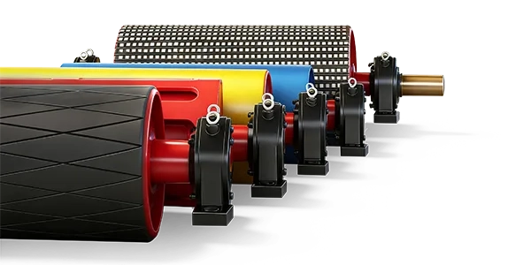
Rubber lagging is widely used for conveyor drive pulleys. Depending on the application, plain, diamond-grooved, or herringbone-patterned rubber can be selected to provide suitable friction and surface behavior.
Grooved lagging may assist water management under appropriate conditions, but the actual groove geometry and operating direction should be considered.
Ceramic Lagging
Ceramic lagging can provide high traction and wear resistance in suitably designed heavy-duty applications. It may be considered where high belt forces, moisture, or abrasive contamination make traction demanding.
However, ceramic lagging is not automatically the best choice for every regenerative conveyor. Its contact behavior, compatibility with the belt cover, bonding system, and operating conditions must be reviewed.
| Lagging Type | Potential Advantage | Selection Consideration |
| Plain Rubber | Straightforward construction and suitable traction in some conditions | Friction and contamination requirements |
| Diamond-Grooved Rubber | Grooved surface with potential drainage benefits | Groove geometry, rubber grade, actual traction |
| Herringbone Rubber | Directional drainage arrangement | Installation orientation and conveyor travel direction |
| Ceramic Lagging | Potentially high traction and wear resistance | Belt compatibility, contact loading, bonding and cost |
For critical regenerative drive pulleys, buyers should request confirmation of lagging suitability under the calculated torque, wrap angle, belt tension, and environmental conditions.
8. Design the Shaft for Bending, Torque and Fatigue
The shaft is one of the most highly stressed components of a heavy-duty drive pulley.
It carries bending loads generated by belt tension and transmits torque between the pulley and the gearbox or other drive components.
On regenerative downhill conveyors, the shaft may experience positive and negative torque depending on the operating mode. Repeated starts, braking events, and torque changes can create fatigue demands that are not represented by a simple static-load calculation.
The shaft design should consider:
- Maximum belt-generated radial loading.
- Maximum motoring and regenerative torque.
- Transient braking and acceleration torque.
- Combined bending and torsional stresses.
- Repeated loading and fatigue life.
- Bearing-center distance and shaft deflection.
- Stress concentrations at shoulders, grooves, and keyways.
- Coupling, gearbox, and brake connection requirements.
For critical applications, shaft calculations should be based on the approved load spectrum and the applicable engineering design requirements.
For related manufacturing and dimensional considerations, see the Conveyor Pulley Shaft and Hub Procurement Guide.
9. Select Hub Connections for Regenerative and Reversing Torque
The hub connection transfers mechanical torque between the pulley shell assembly and the shaft. For a regenerative conveyor, its capacity must be evaluated for the applicable torque directions and load cases.
Keyed Hub Connections
Keyed connections transmit torque through a mechanical key. Their design should account for key and hub strength, shaft geometry, contact conditions, and cyclic loading.
Changes in torque direction can alter contact conditions and may contribute to fretting or fatigue where the connection is unsuitable or poorly fitted.
Keyless Locking Assemblies
Keyless locking assemblies transmit torque through friction generated by controlled clamping forces. They are commonly considered for high-torque industrial drive pulleys.
The selected locking assembly must provide sufficient capacity for the specified torque and any relevant axial loading. Its mating shaft and hub dimensions, surface conditions, material properties, and installation procedures must match the manufacturer’s requirements.
For regenerative applications, verify performance under both positive and negative torque where those conditions occur. Do not assume that nominal torque capacity automatically covers every possible transient or combined loading condition.
10. Evaluate Pulley Shell and End-Disc Strength
The shell and end discs must support belt contact forces and transfer torque between the shell and hub structure.
For heavy-duty regenerative mine conveyors, shell thickness and end-disc design should be based on structural calculations rather than copied from an unrelated pulley with similar dimensions.
Important considerations include shell bending, local deformation, end-disc stresses, hub-to-disc connections, welded joints, fatigue loading, and the effect of pulley diameter and face width.
Large high-tension drive pulleys may require additional engineering verification of critical structural regions. Depending on the design and project requirements, finite-element analysis can supplement conventional structural calculations.
Simply increasing shell thickness without examining the complete load path may add cost and weight without correcting the most critical stress concentration.
11. Understand Regenerative Electrical Drive Requirements
A regenerative conveyor drive system may use variable-speed electric drives capable of controlling both motoring and generating operation.
When the loaded belt drives the motor through the pulley and gearbox, the motor acts as a generator. The resulting energy must be transferred or dissipated through a suitable electrical system.
Possible arrangements include regenerative drives that return energy to the electrical network, common DC-bus arrangements that allow energy sharing, and braking chopper systems that dissipate energy in resistors.
These approaches have different operating and infrastructure requirements. The selected system must support the conveyor’s continuous retarding torque and its actual energy-handling duty.
The pulley manufacturer normally requires the resulting shaft torque, speed, loading, and interface information rather than designing the entire electrical control system.
Nevertheless, close coordination between the pulley manufacturer, drive supplier, conveyor designer, and braking-system engineer is necessary to prevent incompatible mechanical interfaces or overlooked load cases.
12. Mechanical Braking Is a Critical Safety Requirement
Regenerative electrical braking is valuable for controlled operation and energy recovery, but it should not automatically be treated as a complete emergency stopping solution.
A fault affecting the motor, gearbox, power supply, electrical drive, or control system can change or remove the available retarding torque.
Downhill conveyors can therefore require appropriately engineered mechanical brakes and other protective measures capable of controlling credible fault conditions.
Depending on the arrangement, disc brakes may be installed on high-speed drive components, low-speed shafts, or other suitable locations. Brake placement affects the torque transmitted through the gearbox, coupling, and pulley shaft.
The brake system must be evaluated for stopping torque, stopping energy, thermal capacity, holding requirements, response time, redundancy, and credible component failures.
Critical safety distinction: A conventional backstop intended to prevent unwanted reverse belt movement is not automatically capable of stopping a downhill conveyor that is accelerating in its normal forward direction. Regenerative downhill systems require specific assessment of forward overspeed, emergency stopping, holding, and failure scenarios. Safety-critical braking design must be completed by qualified conveyor and braking-system engineers.
13. Why Emergency Braking Loads Can Be More Severe Than Normal Operation
During normal regenerative operation, the drive system supplies controlled retarding torque to maintain the intended belt speed.
During an emergency stop, the braking system must also manage the inertia of the moving belt, conveyed material, and rotating equipment. Depending on the conveyor profile and loading, gravity may continue supplying energy while the conveyor decelerates.
Braking too aggressively can create excessive belt tensions, dynamic oscillations, loss of traction, or damaging loads on pulleys and drive components.
Braking too weakly may result in unacceptable stopping distance, overspeed, or loss of conveyor control.
The required brake torque and deceleration profile must therefore be established through conveyor dynamic analysis and the applicable safety requirements.
Drive pulleys should be checked against the corresponding transient tension and torque values, not only the rated operating values.
14. Multiple Drive Pulleys and Torque Sharing
Long-distance regenerative mining conveyors may use two or more drive pulleys to distribute torque and manage mechanical loads.
Multiple drives can provide flexibility in conveyor design, but they require coordinated speed and torque control.
If the drive system distributes retarding torque unevenly, one pulley may experience higher loads or lower traction margins than intended.
Even when the total regenerative power is known, it should not automatically be divided equally among pulleys unless that load-sharing arrangement is established by design and supported by the control system.
For each drive pulley, specify the individual torque envelope, belt tensions, wrap angle, shaft loads, and expected control behavior.
Also consider credible conditions where one drive or brake becomes unavailable and the remaining components must operate within an approved contingency strategy.
15. Coordinate the Drive Pulley with the Take-Up System
Belt tension is central to both traction and conveyor stability. The take-up system must provide the required tension while accommodating belt elongation and changes during operation.
Depending on conveyor size and design, take-up arrangements may include gravity, winch, or other engineered systems.
In regenerative downhill applications, tension requirements can change between empty motoring, loaded regeneration, startup, and braking.
The selected drive pulley and lagging must maintain sufficient traction at the available take-up tension, while the belt and mechanical components must remain within their allowable loading limits.
Excessively high take-up tension is not a universal solution for insufficient traction. It can increase pulley bearing loads, belt stress, shaft bending, and structural demand.
The drive pulley, take-up system, and conveyor tension distribution should be evaluated as one integrated system.
16. Bearing Selection and Shaft Deflection
Drive pulley bearings must support the actual radial loads, operating speed, shaft movement, and alignment conditions.
In heavy-duty mining applications, suitable rolling-bearing arrangements may be selected according to load, alignment, service life, lubrication, and maintenance requirements.
The shaft’s deflection can influence bearing alignment and the distribution of stress in the pulley structure. Excessive deflection may lead to uneven loading or premature bearing problems.
Regenerative operation should be evaluated under the actual belt tensions and torque loading, including relevant transient conditions.
Dust, moisture, abrasive contamination, and temperature also affect bearing protection and lubrication requirements.
For related information, see How to Minimise Conveyor Pulley Bearing Failure.
17. Inspection and Quality Control for Regenerative Drive Pulleys
Because drive pulleys form part of a critical power-transmission system, manufacturing quality is especially important.
The inspection plan should reflect pulley size, speed, loading severity, fatigue requirements, and project specifications.
| Inspection Item | What to Verify |
| Material Verification | Specified shaft, shell, hub, and end-disc materials |
| Shaft Inspection | Critical diameters, fits, geometry, surface condition |
| Hub and Locking Interface | Bore dimensions, tolerances, mating surfaces, assembly requirements |
| Weld Examination | Specified weld quality and required examination results |
| Lagging Inspection | Material, thickness, pattern, bonding quality |
| Dimensional Accuracy | Pulley face width, runout, shaft positions, bearing-center distance |
| Balancing | Specified balance method and acceptance criteria where required |
| Assembly Verification | Locking elements, couplings, bearings, and applicable interfaces |
Additional nondestructive examination or engineering documentation may be required for critical pulley shafts and welded structures.
Inspection procedures and acceptance criteria should be approved before production rather than introduced after manufacturing is complete.
18. Common Drive Pulley Selection Mistakes on Downhill Conveyors
Mistake 1: Selecting the Pulley from Motor Power Alone
Rated motor power does not define every regenerative and emergency braking torque condition. Use the complete operating and transient torque envelope.
Mistake 2: Ignoring Changes in Belt Tension Direction
When power flows from the belt into the pulley, the incoming and outgoing belt tension relationship differs from conventional motoring operation.
Mistake 3: Assuming Regenerative Braking Replaces Emergency Brakes
Electrical regeneration may become unavailable during certain faults. Emergency stopping and holding requirements must be independently evaluated.
Mistake 4: Using Unverified Lagging Friction Values
Traction assumptions must reflect the actual belt, lagging, moisture, contamination, and loading conditions.
Mistake 5: Ignoring Torque Reversal in Shaft and Hub Design
Where both motoring and regenerative modes occur, torque changes can affect connection fatigue and reliability.
Mistake 6: Assuming Multiple Drives Share Loads Equally
Individual pulley torque must be established from the drive-control and conveyor design, including credible imbalance and failure conditions.
Mistake 7: Omitting Dynamic Conveyor Analysis
Steady-state calculations alone may not identify critical belt tensions, traction loss, or mechanical loads during rapid changes in speed and braking.
19. What Information Should Be Included in the RFQ?
An accurate request for quotation should describe both the pulley construction and its specific regenerative operating duty.
| RFQ Category | Required Information |
| Conveyor Profile | Route length, elevation changes, loaded and return profiles |
| Operating Duty | Material, bulk density, capacity, belt speed, operating schedule |
| Pulley Dimensions | Effective diameter, face width, shaft dimensions, position |
| Torque Requirements | Motoring, regenerative, startup, and transient braking torque |
| Belt Tensions | Incoming and outgoing tension for relevant load cases, minimum tension |
| Traction | Wrap angle, lagging type, operating friction assumptions, wet conditions |
| Drive Arrangement | Number and location of drives, gearbox, coupling, control arrangement |
| Braking Interface | Brake position, torque, connection geometry, applicable fault loads |
| Shaft and Hub | Steel grade, locking assembly, fits, bearing journals, coupling ends |
| Quality Requirements | Drawings, calculations, required NDT, runout, balancing, reports |
| Delivery | Quantity, destination, packaging, delivery schedule |
20. Practical Drive Pulley Procurement Checklist
01. Confirm the downhill conveyor profile and gravitational operating conditions.
02. Identify motoring and regenerative operating modes.
03. Obtain the torque envelope for every drive pulley.
04. Confirm incoming and outgoing belt tensions for all critical cases.
05. Select pulley diameter according to belt and mechanical requirements.
06. Verify wrap angle, lagging friction, and minimum traction margins.
07. Check shaft bending, torsion, fatigue, and deflection.
08. Verify hub connections under applicable torque directions.
09. Confirm shell, end-disc, bearing, and structural loading.
10. Coordinate the mechanical braking interfaces and fault-load requirements.
11. Review multi-drive torque sharing and take-up compatibility.
12. Approve manufacturing drawings and inspection requirements.
13. Confirm packaging, delivery, and replacement installation requirements.
How to Compare Drive Pulley Suppliers for Regenerative Mining Conveyors
A suitable manufacturer should understand that regenerative drive pulleys operate under different power-flow and torque conditions from conventional motor-driven pulleys.
Buyers should compare suppliers based on engineering understanding, drawing capability, shaft and hub manufacturing, structural fabrication, lagging quality, machining accuracy, inspection processes, and documented production controls.
The supplier should be able to review a defined load schedule and identify the critical mechanical requirements of the pulley. Where special calculations or inspection procedures are required, they should be agreed upon before manufacturing.
For replacement projects, matching the original external dimensions is not sufficient if belt capacity, braking equipment, drive controls, or operating conditions have changed.
Engineering responsibility should also be clear. The conveyor designer and braking-system specialists must establish the system-level operating and safety requirements; the pulley manufacturer should manufacture and verify the supplied components against the agreed mechanical specification.
Custom Drive Pulleys for Mining Conveyors from SHENGYUAN
SHENGYUAN supplies conveyor pulleys, rollers, idlers, belts, cleaners, frames, and related components for mining, quarrying, coal handling, cement plants, ports, steel production, power generation, and other heavy-duty bulk-material handling applications.
The SWCONS conveyor pulley range includes drive pulleys, tail pulleys, bend pulleys, take-up pulleys, snub pulleys, and custom pulley configurations with different shaft, hub, and lagging arrangements.
For regenerative downhill mine conveyor projects, pulley manufacturing requirements can be coordinated with approved drawings, operating torque, belt tensions, pulley dimensions, shaft construction, keyless locking assemblies, lagging, bearings, and inspection specifications.
Through custom conveyor solutions, components can be specified to meet project-specific dimensions, installation interfaces, and mechanical requirements.
For international mining projects, manufacturing and delivery requirements can also be coordinated according to the agreed packaging, logistics, and project schedules.
Need a custom drive pulley for a regenerative downhill mining conveyor?
Provide the approved pulley drawing, conveyor profile, belt width and speed, drive arrangement, motoring and regenerative torque values, incoming and outgoing belt tensions, wrap angle, lagging requirements, shaft and hub details, bearing models, braking interfaces, applicable emergency load cases, inspection requirements, and required quantities. These details help establish a technically accurate manufacturing specification for the drive pulley.
Conclusion: Design the Drive Pulley for Regeneration and Braking
Regenerative downhill mine conveyors create demanding operating conditions because the descending material can drive the belt and require continuous controlled braking.
The drive pulley must transmit the required torque while supporting belt tension, maintaining traction, and resisting bending, torsion, fatigue, and transient mechanical loads. Pulley diameter, lagging, shaft design, hub connection, bearings, and shell construction must be selected from the actual operating conditions.
Particular attention should be given to the change in power-flow direction, the influence of braking on belt tensions, and the coordination between multiple drive pulleys and the take-up system.
Regenerative electrical drives can provide valuable energy recovery, but emergency stopping and overspeed protection require their own engineering assessment. The pulley and connected drivetrain must be suitable for the loads generated by the approved braking strategy.
The best drive pulley for a regenerative downhill mine conveyor is not simply one with a large diameter, strong shaft, or high-friction lagging. It is a correctly engineered pulley whose complete mechanical construction matches the conveyor’s regenerative torque, belt tension, traction, braking dynamics, and long-term operating requirements.