



Choosing conveyor pulleys for tandem mine conveyor drives requires careful evaluation of drive torque, belt tension, traction, shaft strength, and the way mechanical power is distributed between the primary and secondary drive pulleys. This becomes particularly important when the two drives do not share the load equally.
Tandem drive arrangements are widely considered for heavy-duty mining conveyors that require substantial driving force. By using two powered pulleys, the conveyor can distribute the required driving effort across multiple belt-contact surfaces instead of relying on a single drive pulley.
However, two pulleys installed in the same drive station do not necessarily transmit equal torque. The actual load distribution depends on the drive-control strategy, motor characteristics, gearbox configuration, pulley effective diameters, belt tensions, lagging properties, and operating conditions.
A tandem drive designed around an assumed 50:50 load distribution may develop problems if one pulley regularly transmits substantially more torque than the other. These problems can include premature shaft fatigue, locking assembly movement, lagging deterioration, traction loss, bearing overload, and unexpected changes in belt tension.
For mining operations transporting iron ore, copper ore, coal, limestone, and other bulk materials, the correct pulley specification must consider individual drive torque, actual load sharing, belt tension at each pulley, wrap angle, lagging traction, shaft and hub capacity, dynamic operating loads, and coordination between the mechanical and electrical drive systems.
Quick answer: Select primary and secondary pulleys for tandem mine conveyor drives using their individual maximum torque and belt tension requirements, not an assumed equal share of total motor power. Calculate the belt tension differences across both pulleys, verify traction separately for each contact surface, and evaluate the effects of unequal loading during startup, steady operation, stopping, and drive faults. Shaft, hub, shell, bearings, lagging, and locking assemblies must be designed for the approved load envelope. Actual load sharing should also be verified through the drive-control design and commissioning measurements.
What Is a Tandem Drive in a Mine Belt Conveyor?
A tandem conveyor drive uses two powered pulleys arranged along the belt path to transmit driving force to the conveyor belt.
The arrangement may include separate motors and gearboxes for the two pulleys, or another engineered drivetrain configuration. In either case, both pulley contact surfaces contribute to transmitting mechanical power between the drive system and the conveyor belt.
The primary and secondary drive pulleys are not necessarily identical in their mechanical loading, even if their external dimensions appear the same.
In a typical motoring arrangement, the primary pulley receives the belt at a higher tension. As the belt passes around the driven pulleys, each pulley contributes a portion of the total required effective driving force.
The secondary pulley normally operates at a different tension level because the primary pulley has already transferred part of the required driving effort to the belt.
Tandem drives can offer several engineering advantages:
- Distribution of the total driving effort across two powered pulleys.
- Additional effective belt-to-pulley contact for transmitting traction.
- Potential reduction in required maximum belt tension through an appropriately designed drive arrangement.
- Flexibility in selecting motors, gearboxes, and pulley configurations.
- Opportunities to manage operating loads through coordinated drive controls.
These benefits depend on correct engineering. An unsuitable torque distribution can overload one pulley while the other contributes less driving force than intended.
1. Understand Why Tandem Drives May Share Loads Unequally
Unequal load sharing occurs when the primary and secondary drives transmit different portions of the total conveyor driving effort.
In some systems, unequal sharing is intentional. The conveyor designer may assign different torque demands to the two pulleys to achieve a suitable belt tension distribution or to match different installed drive capacities.
In other systems, unequal sharing is unintended. It may result from drive-control differences, mechanical characteristics, equipment wear, or operating variations.
| Cause of Unequal Sharing | Possible Effect | What to Check |
| Different Motor Torque Commands | One drive contributes more effort | Drive settings and torque references |
| Different Effective Pulley Diameters | Different surface speeds at equal shaft speeds | Pulley and lagging dimensions |
| Gearbox or Motor Characteristics | Different torque-speed responses | Gear ratios, efficiencies and motor data |
| Lagging Wear or Contamination | Different traction behavior | Lagging condition and belt slip |
| Unequal Drive Ratings | Intentionally different power contributions | Approved design torque allocation |
| Transient Operating Conditions | Temporary torque imbalance | Starting, stopping and fault records |
The important distinction is whether unequal sharing is part of the approved design or an operating condition that exceeds the intended load distribution.
2. Do Not Assume a 50:50 Torque Distribution
A common purchasing mistake is specifying two identical drive pulleys because the tandem system uses two motors with similar rated power.
Equal motor nameplate ratings do not guarantee equal actual torque at the pulley shafts. Mechanical losses, gearbox ratios, control settings, operating conditions, and equipment characteristics can affect the delivered torque.
For example, a conveyor designed for nominal equal sharing may experience periods when one pulley contributes 60% or 70% of the total driving effort while the other carries the remainder.
These percentages are illustrative examples, not universal design allowances.
Before approving pulley specifications, the conveyor designer should provide the expected sharing range and the maximum applicable torque for each drive pulley.
Key engineering principle: Tandem drive pulleys should be checked against the maximum individual loads they may actually experience. A nominal 50:50 drive allocation is not a substitute for the approved torque-sharing and dynamic load analysis.
3. Calculate the Effective Driving Force at Each Pulley
The driving force transmitted by an individual pulley depends on the difference between the belt tensions at its two sides.
For a simplified tandem arrangement operating in the motoring direction, consider the belt passing around the first drive pulley and then the second drive pulley.
Let the belt tensions at the three successive locations be T0, T1, and T2, where T0 is the higher-tension side and T2 is the lower-tension side.
Primary Pulley Driving Force = T0 − T1
Secondary Pulley Driving Force = T1 − T2
Total Driving Force = T0 − T2
These relationships show that the total effective driving force is the sum of the contributions from the two pulleys.
However, the intermediate belt tension T1 changes when the torque distribution changes. This means unequal sharing affects more than shaft torque; it also changes the belt tensions and traction conditions experienced by each drive pulley.
For regenerative operation or other torque directions, the tension relationships must be established using the actual direction of power transfer.
4. Example: A Tandem Drive with 65:35 Load Sharing
Consider a simplified mine conveyor tandem drive with a total effective driving force of 120 kN.
Assume that the primary pulley transmits 65% of this force and the secondary pulley transmits 35%.
For this example, both pulleys have an effective diameter of 1000 mm.
| Parameter | Primary Pulley | Secondary Pulley |
| Drive Share | 65% | 35% |
| Effective Driving Force | 78 kN | 42 kN |
| Effective Pulley Diameter | 1000 mm | 1000 mm |
| Effective Radius | 0.5 m | 0.5 m |
| Steady-State Pulley Torque | 39 kN·m | 21 kN·m |
The primary pulley transmits substantially more torque even though both pulleys have the same effective diameter.
If the belt tensions are 200 kN before the primary pulley, 122 kN between the pulleys, and 80 kN after the secondary pulley, the tension differences correspond to the stated 78 kN and 42 kN driving forces.
This example illustrates an important design point: the primary and secondary pulleys can experience different torque and belt tension loads even when the total conveyor driving requirement remains unchanged.
The calculations represent a simplified steady-state mechanical case. They do not include drive losses, transient torque, emergency braking, or individual pulley traction limits. They are not sufficient for final equipment design.
5. Calculate the Individual Shaft Torque, Not Only Total Drive Power
For each drive pulley, the transmitted shaft torque can be estimated from the effective driving force and pulley radius.
Drive Pulley Torque = Effective Driving Force × Effective Radius
Torque: N·m; Effective Driving Force: N; Effective Radius: m.
Pulley torque is influenced by the force transmitted through belt contact and the effective pulley diameter, including the relevant lagging thickness.
If the two pulleys have different effective diameters, equal driving-force contributions do not necessarily mean equal shaft torques. Likewise, equal shaft torque does not necessarily mean equal drive power when pulley rotational speeds differ.
The supplier should receive the specified mechanical torque at the pulley shaft, not simply the electrical power rating of the connected motor.
For critical mine conveyor applications, the specification should distinguish continuous torque, expected maximum operating torque, temporary overload torque, starting torque, and applicable braking torque.
6. Check Traction Separately for Primary and Secondary Pulleys
Drive torque must be transferred to the belt through friction between the pulley surface and the belt cover.
In a tandem drive, the two pulleys may operate with different belt tension ratios, wrap angles, effective diameters, and lagging conditions.
Therefore, the traction available at each pulley must be verified independently.
A simplified capstan relationship can be used for preliminary assessment:
Thigh / Tlow ≤ eμθ
Thigh: Higher belt tension; Tlow: Lower belt tension; μ: Assumed friction coefficient; θ: Wrap angle in radians.
This simplified model illustrates why pulley wrap and friction influence the maximum tension ratio that can be transmitted without gross slip.
However, the friction coefficient is not a universal constant. Actual traction depends on lagging type, belt cover, moisture, contamination, contact pressure, surface wear, and other operating conditions.
For a tandem drive, the check should use the actual tensions on both sides of each pulley for every relevant load-sharing condition.
Critical requirement: A tandem drive with sufficient combined traction may still experience slip at one individual pulley. The traction capacity of one pulley cannot automatically compensate for insufficient traction at the other without changing the operating load distribution.
7. Why the Secondary Drive Pulley Can Have a Different Traction Limit
In a typical motoring tandem arrangement, the belt tension decreases as driving effort is transferred through successive powered pulleys.
The secondary pulley may therefore operate with lower absolute belt tensions than the primary pulley. Depending on wrap angle and lagging conditions, this can influence the driving force it can transmit without slip.
If the secondary drive is commanded to transmit a greater torque than its available traction permits, localized slip may develop even if the primary pulley continues operating normally.
The solution is not necessarily to install the same high-friction lagging on both pulleys. Engineers should evaluate whether the secondary pulley needs different lagging, a different wrap angle, a revised torque allocation, or a change in the approved take-up tension.
Increasing the load assigned to one drive also changes the intermediate belt tension, which can alter the traction requirements of both pulleys.
The tandem drive must therefore be assessed as an interconnected system rather than as two mechanically independent pulleys.
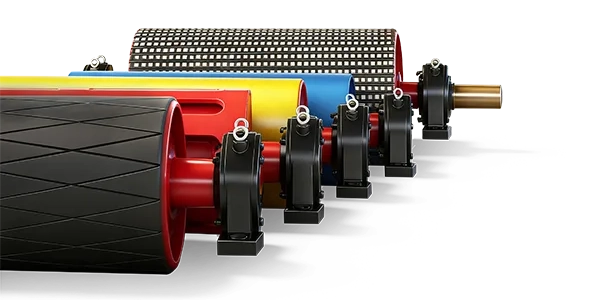
8. Select Rubber or Ceramic Lagging Based on Actual Loads
Lagging improves contact between the pulley and belt and protects the pulley shell from wear. Its selection is especially important where torque sharing is unequal or changes during operation.
Plain Rubber Lagging
Plain rubber lagging can provide suitable traction in some dry or moderate-duty applications. Its performance depends on the rubber formulation, hardness, surface condition, and operating environment.
Diamond-Grooved Rubber Lagging
Diamond-grooved lagging provides a patterned contact surface and can help manage water or certain contaminants, depending on the groove design and application.
It is commonly considered for heavy-duty mining conveyors where drainage and reliable traction are important.
Herringbone Rubber Lagging
Herringbone lagging uses a directional groove pattern. The groove orientation should match the intended operating direction and drainage requirements.
Ceramic Lagging
Ceramic lagging can provide high traction and strong wear resistance in suitably engineered mining applications. It may be considered where one pulley experiences a demanding torque requirement or operates under wet, contaminated conditions.
However, ceramic lagging is not automatically the best choice for both tandem pulleys. The actual belt contact conditions, required traction, lagging bond, belt cover compatibility, and operating environment must be evaluated.
| Lagging Type | Potential Benefit | Important Consideration |
| Plain Rubber | Straightforward construction and suitable traction for selected duties | Required friction and environmental conditions |
| Diamond Rubber | Grooved contact surface and potential drainage benefits | Rubber quality, groove pattern and wear |
| Herringbone Rubber | Directional drainage arrangement | Groove direction and belt travel |
| Ceramic Lagging | Potentially high traction and wear resistance | Contact behavior, bond strength and belt compatibility |
For more information on lagging patterns, see Conveyor Pulley Lagging: Plain, Herringbone or Diamond?
9. Check Effective Pulley Diameter and Speed Compatibility
Effective pulley diameter is an important consideration in tandem drives because it affects the relationship between shaft speed and belt surface speed.
Two pulleys with the same nominal steel shell diameter may have different effective outside diameters after lagging is installed.
Differences can also develop as lagging wears or is replaced.
For a given shaft rotational speed, the peripheral speed of the pulley depends on its effective diameter. Therefore, two tandem pulleys operating at the same rotational speed but with different effective diameters may tend to produce different surface speeds.
Whether this creates unwanted torque redistribution depends on the drivetrain, motor controls, belt elasticity, and contact behavior.
For new pulleys and replacement projects, verify:
- Steel shell outside diameter.
- Specified lagging thickness.
- Finished effective pulley diameter.
- Permitted dimensional tolerances.
- Gearbox output speed and gear ratio.
- Motor and drive-control speed requirements.
- Operating differences caused by lagging wear.
A replacement pulley should not be approved solely because its nominal diameter matches the old component. The finished effective diameter and associated drivetrain requirements must also be checked.
10. Design Pulley Shafts for Unequal Torque and Fatigue
The drive pulley shaft transmits torque while carrying bending loads from belt tension and the mechanical arrangement.
When a tandem drive operates with unequal loading, the shaft of one pulley may experience greater torsional demand than originally expected from a nominal equal-sharing assumption.
Repeated changes in torque can also affect fatigue loading. This is particularly important for mine conveyors operating continuously with frequent production changes, loaded starts, or controlled braking events.
The shaft design should evaluate:
- Maximum continuous operating torque.
- Temporary overload and transient torque.
- Combined bending and torsion.
- Rotating bending fatigue.
- Torque fluctuations and applicable load reversals.
- Shaft shoulders, grooves and other stress concentrations.
- Bearing-center distance and shaft deflection.
- Coupling and gearbox connection geometry.
The primary and secondary shafts may require different dimensions or materials where their approved loads differ. Identical construction can still be selected where both pulleys are verified for the required load cases.
The objective is not simply to increase shaft diameter. A suitable design must address the complete load path, fatigue requirements, connection interfaces, and acceptable deflection.
11. Verify Keyless Locking Assemblies and Hub Connections
The hub connection transfers torque between the pulley structure and the shaft.
In heavy-duty conveyor pulleys, this connection may use keyed hubs, keyless locking assemblies, or other engineered arrangements.
Keyless locking assemblies use clamping pressure and friction to transmit mechanical torque. They can be useful for high-torque applications when correctly selected and installed.
However, their capacity must be verified against the maximum torque assigned to the individual pulley, including the appropriate overload conditions and any relevant axial loads.
If one tandem drive transmits substantially more torque than the other, the same locking assembly size may not provide an equivalent utilization margin on both pulleys.
Important checks include:
- Maximum required connection torque.
- Approved overload and torque reversal conditions.
- Shaft and hub material properties.
- Bore diameter and dimensional tolerances.
- Surface condition and assembly requirements.
- Locking assembly manufacturer’s installation instructions.
- Inspection access and future disassembly requirements.
Incorrect tightening, unsuitable mating surfaces, or a connection selected below the required torque capacity can lead to movement or damage at the hub interface.
12. Evaluate Shell Thickness and End-Disc Strength
The pulley shell and end discs transfer driving forces from the hub structure to the belt-contact surface while supporting the applied belt loads.
A tandem drive pulley experiencing high torque may require particular attention to shell stresses, end-disc stresses, hub connections, and welded joints.
Unequal load sharing can alter torsional demands, but shell and end-disc selection must also account for bending and local contact forces created by belt tension and wrap geometry.
These structural loads should be determined from the actual pulley position and mechanical arrangement rather than assuming that the pulley carrying the smaller torque always has the smaller structural demand.
For critical high-tension pulleys, engineering calculations and finite-element analysis may be appropriate to investigate structural stress concentrations and fatigue-sensitive regions.
Simply selecting a thicker shell without checking the shaft, hub, end discs, and weld design does not guarantee a stronger complete pulley.
13. Select Bearings from the Actual Belt Tension Forces
Bearing selection is closely related to the belt tensions and wrap geometry at each drive pulley.
Because the primary and secondary pulleys may operate at different belt tension levels, their shaft bearing loads may also differ significantly.
The bearing reaction should be established from the vector result of the belt forces and other relevant mechanical loads. It should not automatically be calculated as a simple arithmetic sum of the two belt tensions without considering their directions.
Bearing selection should consider radial loading, applicable axial loading, shaft speed, required life, alignment, lubrication, operating temperature, and contamination conditions.
For outdoor mining applications, dust and moisture protection are also important. Inadequate sealing or contaminated lubrication can reduce bearing reliability even when the basic load rating is sufficient.
The two tandem pulleys may use different bearing arrangements if their actual loading or interfaces require it. Where common components are preferred for spare-parts standardization, the shared design must satisfy the more demanding applicable requirements.
14. Coordinate the Mechanical Pulley Design with the Drive Controls
Tandem drive load sharing depends partly on the electrical and mechanical control system.
Depending on the installation, the conveyor may use variable-frequency drives, controlled-start equipment, fluid couplings, or other drivetrain configurations.
Drive coordination can influence how torque is distributed during steady operation and changes in conveyor speed.
For example, a system with coordinated variable-speed drives may be designed to regulate motor torque contributions according to an approved sharing strategy.
However, the actual mechanical torque delivered at the pulley shaft still depends on motor behavior, gearbox efficiency, operating speed, and the functioning of the control system.
Pulley manufacturers should coordinate with conveyor and drive-system engineers to obtain the approved torque envelope rather than attempting to determine the electrical control strategy from pulley dimensions alone.
Particular attention should be given to control conditions in which one drive reaches a torque limit or does not respond as expected. The resulting redistribution of torque may increase the load on the other pulley.
15. Startup Can Create Temporary Torque Imbalance
Startup is one of the operating conditions that can produce temporary differences in tandem drive torque.
When a conveyor accelerates, the drive system must overcome the resistance to motion and accelerate the rotating equipment, belt, and conveyed material.
The belt’s longitudinal elasticity also affects how tension changes propagate through the conveyor.
If one drive develops torque more quickly than the other, a temporary difference in torque contribution may occur.
This can alter the intermediate belt tension between the two drive pulleys and affect local traction requirements.
An appropriate startup-control strategy should manage the acceleration profile and torque allocation so that the belt and mechanical equipment remain within their approved limits.
For pulley selection, request the maximum startup torque and corresponding belt tensions for each pulley, not just the normal running values.
16. Stopping and Emergency Braking Must Also Be Evaluated
Stopping conditions can introduce additional mechanical loads into the tandem drive system.
Depending on conveyor geometry, operating load, and the braking arrangement, individual drive pulleys may experience different retarding torque contributions during deceleration.
Emergency braking can also generate transient belt tension changes that differ substantially from steady-running conditions.
These events may affect pulley traction, shaft loading, hub connections, and the mechanical load carried by each drive station component.
The braking system should be designed by qualified conveyor and braking-system engineers using the required operating and fault scenarios.
The pulley supplier should receive the resulting torque and tension requirements for the components it manufactures.
Safety consideration: Do not assume that two tandem drive pulleys will continue sharing torque equally during emergency braking or failure of one drive. The braking strategy, pulley loading, belt tensions, and available traction must be assessed for the credible fault conditions defined by the conveyor safety design.
17. Consider the Consequences of One Drive Becoming Unavailable
A tandem drive may experience a condition in which one motor, gearbox, coupling, electrical drive, or related component is unavailable.
Whether the remaining drive can continue operation depends on the conveyor design and approved contingency strategy.
It is unsafe to assume that the remaining pulley can automatically transmit the entire original driving force simply because it is mechanically connected to the same conveyor belt.
The remaining drive must have adequate motor and gearbox capacity, shaft and hub strength, traction margin, and suitable belt tension conditions for any permitted reduced-drive operation.
Some installations may require a controlled stop rather than continued operation when one drive becomes unavailable.
Backstops and mechanical brakes also require separate assessment. Load sharing between these devices cannot automatically be assumed to match the normal motor torque distribution.
For critical applications, the equipment manufacturer should receive the maximum mechanical loads resulting from the approved failure scenarios rather than an arbitrary overload percentage.
18. Why the Take-Up System Matters to Tandem Drive Load Sharing
The take-up system maintains the belt tension needed for suitable traction and belt support.
For a tandem drive, take-up tension influences the lower-tension side of the drive arrangement and therefore affects the available traction at each pulley.
When load sharing changes, the intermediate tension between the primary and secondary pulleys can also change. The traction margin available at each pulley may therefore vary even if the take-up setting remains unchanged.
Increasing the take-up force can sometimes improve traction, but it also increases loads on the belt, pulleys, bearings, and structure.
The correct solution must consider the entire belt tension distribution, allowable belt stresses, drive torque requirements, and pulley contact conditions.
A tandem drive should not be adjusted by increasing take-up tension simply to compensate for unverified torque sharing or deteriorated lagging.
19. Common Tandem Drive Problems and Their Possible Causes
| Observed Problem | Possible Cause | Recommended Investigation |
| Primary Drive Motor Consistently Carries More Load | Approved unequal sharing or control mismatch | Compare actual torque with design allocation |
| Slip at Secondary Pulley | Insufficient local traction or excessive torque demand | Check belt tensions, wrap, lagging and torque commands |
| Uneven Lagging Wear | Different contact loads, slip or contamination | Inspect lagging and review traction conditions |
| Excessive Shaft or Hub Movement | Overload, insufficient connection capacity or assembly problem | Verify maximum torque and hub installation |
| Bearing Overheating | High radial load, lubrication issue or misalignment | Check bearing reaction, alignment and lubrication |
| Torque Imbalance During Startup | Drive response or control coordination differences | Review synchronized drive and conveyor data |
| Repeated Lagging Bond Failure | Mechanical overload, preparation or bonding deficiency | Inspect bond, shell preparation and operating loads |
These symptoms are not definitive evidence of unequal load sharing. A proper investigation should combine electrical drive records, mechanical inspection, belt tension information, and pulley condition measurements.
20. How to Measure Actual Load Sharing During Operation
For an existing mine conveyor, measured operating data can help determine whether the tandem drives perform according to the approved design.
Useful records may include motor torque estimates, drive output power, rotational speed, gearbox information, belt speed, material throughput, and take-up operating conditions.
Where possible, these values should be recorded on a common time basis during representative empty, partially loaded, fully loaded, starting, and stopping conditions.
However, electrical current alone should not be treated as a direct measurement of pulley shaft torque. Motor characteristics, drive-control algorithms, electrical power factors, gearbox efficiency, and other conditions influence the relationship.
Drive torque estimates should be validated according to the electrical drive manufacturer’s methods or through appropriate mechanical measurements when required.
For a replacement project, actual torque data may reveal that a pulley has regularly operated above the nominal load originally assigned to it.
This information can help determine whether the new pulley requires a revised mechanical specification or whether the underlying load-sharing issue should be corrected through the conveyor drive system.
21. Quality Control for Heavy-Duty Tandem Drive Pulleys
Manufacturing quality is important for any drive pulley, but it becomes particularly valuable in tandem drives where torque distribution and surface-speed compatibility must be controlled.
For demanding mining applications, the inspection plan should address the relevant mechanical loads, operating speed, structural requirements, and installation interfaces.
| Inspection Item | What to Verify |
| Shaft Material | Specified steel grade, dimensions and relevant material documentation |
| Shell and End Discs | Dimensions, fabrication quality and approved structural details |
| Weld Examination | Specified weld quality and applicable examination results |
| Hub and Locking Assembly | Bore tolerances, shaft fits and connection requirements |
| Finished Effective Diameter | Outside diameter after lagging, where required for drive coordination |
| Lagging Quality | Material, thickness, groove pattern, bonding and surface condition |
| Runout and Alignment | Approved shell and shaft dimensional tolerances |
| Balancing | Specified balancing method and acceptance criteria where applicable |
| Final Documentation | Approved drawings, inspection records and identification |
For new tandem pulleys, it may be beneficial to coordinate the finished diameter tolerances and lagging specifications of the complete pulley set during manufacturing.
This does not eliminate the need for correct drive controls, but it can help reduce avoidable mechanical differences between the two pulley assemblies.
22. What Information Should Be Included in the RFQ?
A detailed request for quotation is essential when ordering tandem drive pulleys for a mine conveyor with unequal load sharing.
A general statement such as “two drive pulleys for a 500 kW conveyor” is not enough to determine the actual mechanical requirements of each pulley.
| RFQ Category | Required Information |
| Conveyor Details | Material, capacity, conveyor length, elevation and belt speed |
| Tandem Drive Arrangement | Primary and secondary pulley locations, belt path and drive layout |
| Drive Equipment | Motor ratings, gearbox ratios, coupling details and control arrangement |
| Torque Sharing | Nominal distribution, maximum expected imbalance and individual load envelopes |
| Pulley Torque | Continuous, starting, maximum transient and braking torque for each pulley |
| Belt Tensions | Incoming and outgoing tension at both pulleys for relevant operating cases |
| Traction Requirements | Wrap angle, friction assumptions, minimum tension and contamination conditions |
| Pulley Dimensions | Steel shell diameter, finished diameter, face width and shaft drawings |
| Shaft and Hub | Material grade, locking assembly, connection type and shaft end dimensions |
| Bearing Arrangement | Calculated loads, bearing models, housings and lubrication requirements |
| Lagging Requirements | Rubber or ceramic type, thickness, hardness and groove configuration |
| Quality Requirements | Material certification, welding inspection, runout, balancing and test documentation |
| Commercial Details | Quantity, identification, drawings, packaging, delivery date and destination |
23. Practical Tandem Drive Pulley Selection Checklist
01. Confirm the primary and secondary drive pulley arrangement.
02. Identify the approved nominal and maximum load-sharing conditions.
03. Obtain individual torque requirements for each pulley.
04. Calculate incoming and outgoing belt tensions at both pulleys.
05. Verify wrap angle and traction independently for each pulley.
06. Select suitable rubber or ceramic lagging for the actual duty.
07. Confirm effective pulley diameters and drivetrain speed compatibility.
08. Check shaft bending, torsion, fatigue and deflection.
09. Verify hubs and locking assemblies under peak torque.
10. Review shell, end-disc, weld and bearing requirements.
11. Evaluate startup, stopping and applicable emergency load cases.
12. Coordinate with the electrical drive and take-up system design.
13. Confirm the approved response to loss of one drive.
14. Approve manufacturing drawings and inspection requirements.
15. Verify actual operating load sharing during commissioning.
24. Common Mistakes When Selecting Tandem Drive Pulleys
Mistake 1: Assuming Both Drives Always Share Torque Equally
Actual torque distribution may differ from nominal motor ratings. The pulleys must be checked against the approved load-sharing envelope.
Mistake 2: Selecting Both Pulleys from Total Drive Power Alone
Total motor power does not define each pulley shaft’s maximum torque or the intermediate belt tension between the pulleys.
Mistake 3: Checking Only Combined Traction
Each pulley has its own tension ratio, wrap angle and lagging characteristics. Insufficient traction at one pulley can create slip even when the overall drive arrangement appears adequate.
Mistake 4: Ignoring Finished Pulley Diameter Differences
Lagging thickness and effective diameter differences can influence pulley surface speed and drivetrain interaction.
Mistake 5: Using Identical Shaft and Hub Designs Without Verification
Standardizing components can simplify maintenance, but both pulley assemblies must be suitable for their maximum actual loads.
Mistake 6: Ignoring Torque Redistribution During Startup
One drive may temporarily transmit more torque because of differences in motor response or drive control. Startup requirements must be part of the approved design.
Mistake 7: Assuming One Pulley Can Automatically Replace the Other Drive
Operation with one unavailable drive requires specific motor capacity, traction, tension and safety assessment. It should not be assumed from the presence of two powered pulleys.
Mistake 8: Treating Unequal Sharing as a Pulley Problem Alone
Unequal load sharing may originate from control settings, gear ratios, motor characteristics, lagging conditions, or other system factors. Replacing the pulley without investigating these causes may not resolve the problem.
How to Compare Tandem Drive Pulley Suppliers
For heavy-duty mine conveyor applications, supplier evaluation should focus on engineering understanding, manufacturing accuracy, shaft and hub construction, lagging quality, and the ability to meet project-specific mechanical specifications.
A suitable supplier should understand that the primary and secondary pulleys may operate at different torque and belt tension levels. The quotation should therefore identify each pulley’s approved loading and construction requirements.
Important comparison factors include steel material quality, precision machining, welding inspection, locking assembly selection, lagging bonding, dimensional control, balancing requirements, and complete manufacturing records.
Where the customer requires identical replacement pulleys, the manufacturer should confirm that both units meet the more demanding applicable loading conditions and installation interfaces.
For further technical considerations, see How to Choose Drive Pulleys for Heavy-Duty Conveyors.
Custom Tandem Drive Pulleys for Mining Conveyors from SHENGYUAN
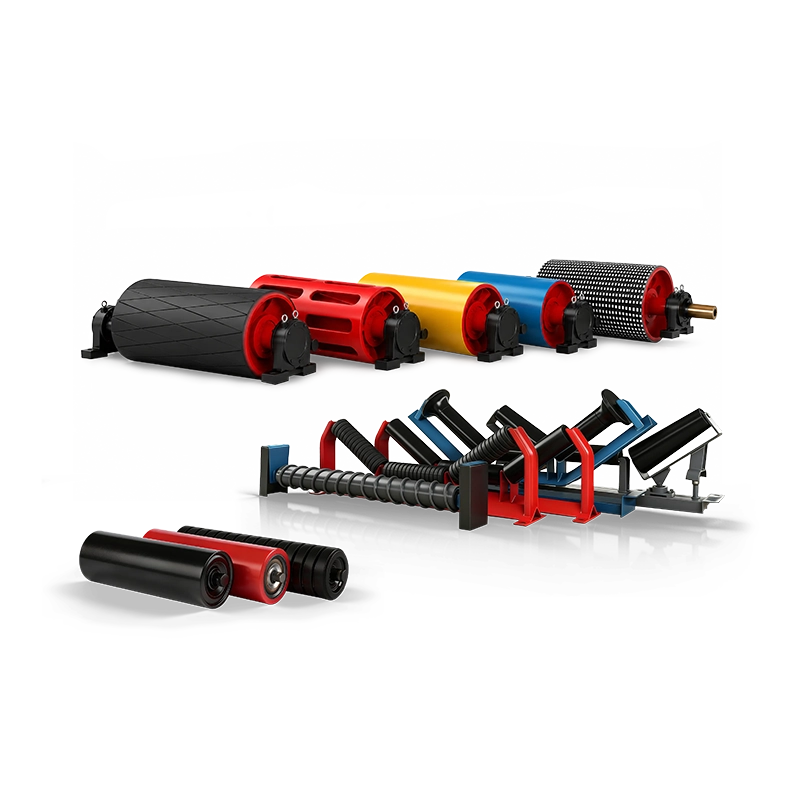
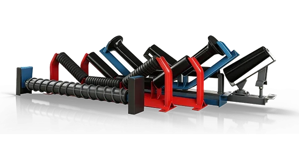
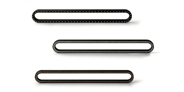
SHENGYUAN manufactures conveyor pulleys, rollers, idlers, frames and related heavy-duty bulk-material handling components for mining, quarrying, coal handling, ports, cement plants, steel production, power generation and other industrial applications.
The SWCONS conveyor pulley range includes drive pulleys, tail pulleys, bend pulleys, snub pulleys, take-up pulleys, rubber-lagged pulleys, ceramic-lagged pulleys and custom heavy-duty pulley constructions.
For tandem mine conveyor drives, pulley manufacturing requirements can be coordinated according to approved shaft torque, belt tensions, wrap angle, pulley diameter, face width, shaft material, hub connection, bearing arrangement, lagging construction and inspection specifications.
Keyless locking assemblies, custom shaft-end configurations, different lagging patterns, and application-specific dimensions can be considered according to the approved project requirements.
Through custom conveyor solutions, components can be manufactured according to customer drawings and coordinated with existing belt, gearbox, coupling, bearing and structural interfaces.
For replacement projects, detailed operating information and previous failure records are particularly valuable. They can help identify whether the original pulley specification remains suitable for the current mine production and drivetrain arrangement.
Need custom pulleys for a tandem mine conveyor drive?
Send the approved tandem drive layout, pulley drawings, belt width and speed, motor and gearbox specifications, nominal and maximum torque-sharing requirements, individual pulley torque values, belt tensions at each pulley, wrap angles, lagging requirements, shaft and hub details, bearing specifications, startup and braking loads, inspection requirements and required quantities. These details provide a stronger basis for accurately specifying both the primary and secondary drive pulleys.
Conclusion: Design Each Tandem Drive Pulley for Its Actual Load
Tandem drive systems can provide important benefits for long-distance and high-capacity mine conveyors by distributing driving effort across multiple powered pulleys.
However, the primary and secondary pulleys do not necessarily share torque equally. Differences in drive controls, motor characteristics, effective pulley diameter, lagging condition and operating loads can change the actual mechanical demand on each component.
Correct selection begins with the individual torque and belt tension requirements of each pulley. Traction should then be checked separately using the actual wrap angles, lagging properties and relevant operating conditions.
Shaft strength, hub connection capacity, shell design, end-disc stresses, bearings and manufacturing tolerances must all match the approved load envelope, including relevant startup, stopping and fault conditions.
A well-engineered tandem drive also requires coordination between the conveyor designer, electrical drive supplier, braking-system engineer and pulley manufacturer.
The best pulley selection for a tandem mine conveyor drive is not simply two identical drums rated for half the total motor power. It is a coordinated primary and secondary pulley design that accounts for actual torque distribution, intermediate belt tension, individual traction limits, transient loading and long-term mechanical reliability.