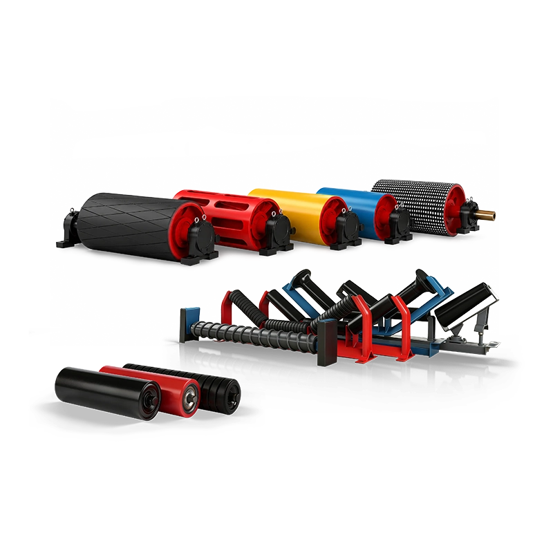
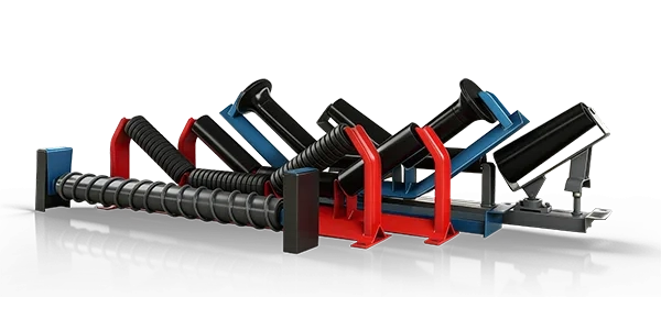
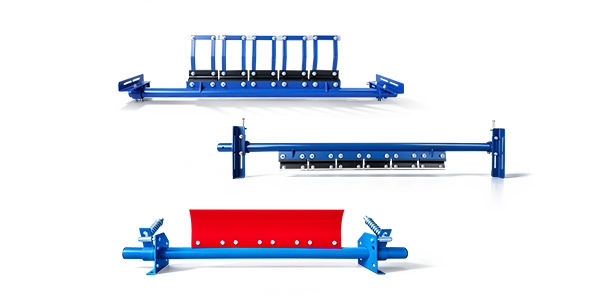



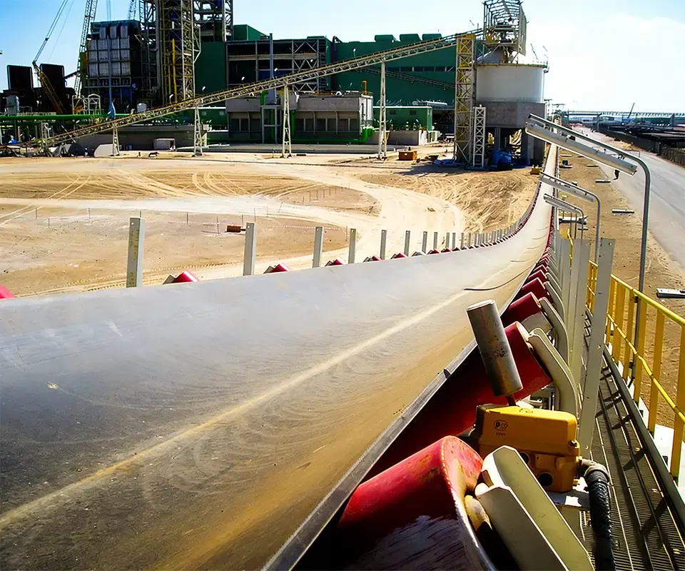

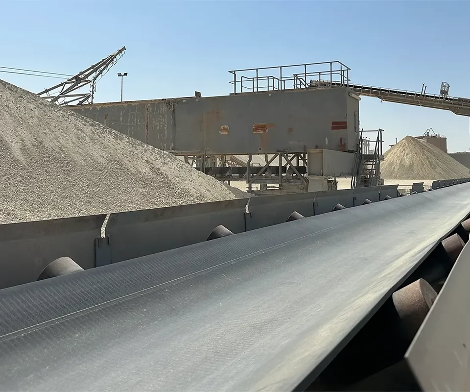
Conveyor idler frames are essential structural components in belt conveyor systems. They support the rollers, establish the required belt profile, maintain roller alignment, and transfer loads into the conveyor structure. Although an idler frame may appear to be a relatively simple welded steel assembly, incorrect mounting dimensions or roller positions can create significant installation and operating problems.
For mining, quarrying, cement, coal handling, ports, power plants, and other bulk-material applications, purchasing replacement idler frames requires more than specifying belt width and trough angle. Two frames designed for the same conveyor belt width may have different mounting-hole centers, base widths, roller lengths, shaft supports, installation heights, and structural arrangements.
These differences become particularly important when replacing existing frames without modifying the conveyor structure. A frame that does not maintain the original belt line can introduce excessive belt stress, tracking problems, material spillage, or interference with adjacent equipment.
A reliable procurement specification should therefore cover mounting dimensions, bolt-hole patterns, frame height, trough angle, roller positions, shaft-end compatibility, structural load capacity, manufacturing tolerances, corrosion protection, and interchangeability verification.
Quick answer: When buying conveyor idler frames, do not order from belt width alone. Confirm the frame type, trough angle, overall width, mounting-hole spacing, hole size, mounting height, roller lengths, shaft-end supports, and existing belt-line position. For replacement projects, request an approved drawing and verify that the new frame can fit the existing structure and rollers without drilling, welding, or changing the conveyor geometry.
What Is a Conveyor Idler Frame?
A conveyor idler frame is the structural assembly that holds one or more idler rollers in the correct position. It may include a base member, roller-support brackets, shaft mounting points, stiffeners, and attachment holes.
The frame determines the position and orientation of the rollers relative to the belt and conveyor structure. It must support normal operating loads while maintaining sufficient alignment and stiffness.
Different frame configurations are used for carrying, impact, transition, self-aligning, and return idlers. Each type has different dimensional and functional requirements.
For an overview of roller and idler arrangements, see Conveyor Idler Types and Their Applications.
1. Identify the Frame Type Before Measuring Dimensions
The first purchasing step is to identify the function of the existing frame. A three-roll troughing frame should not be treated as interchangeable with an impact frame or a transition frame simply because both support the same belt width.
| Frame Type | Primary Function | Critical Interface |
| Troughing Carrying Frame | Supports the loaded belt | Trough angle, roller positions, frame height |
| Impact Idler Frame | Supports the belt beneath loading zones | Structural stiffness, load capacity, roller clearance |
| Transition Idler Frame | Gradually changes belt profile near pulleys | Transition angle and roller elevation |
| Self-Aligning Frame | Provides tracking assistance | Pivot arrangement and movement clearance |
| Return Idler Frame | Supports the empty return belt | Mounting orientation, shaft supports, belt elevation |
For procurement, record the frame type and conveyor location before selecting dimensions. This helps prevent visually similar but functionally different frames from being ordered.
2. Belt Width Does Not Define the Complete Frame
Belt width is an important starting point, but it is not sufficient to establish frame interchangeability.
For example, two three-roll idler sets designed for a 1000 mm belt may use different roller lengths, mounting centers, shaft supports, and frame elevations. One may fit the existing conveyor structure while the other requires modifications.
Manufacturers may also use different bracket arrangements to achieve the same nominal trough angle.
A replacement frame should be selected from the actual installation dimensions, not solely from the nominal belt size.
3. Measure Mounting-Hole Centers Accurately
Mounting-hole dimensions are among the most important details when purchasing replacement idler frames.
The procurement drawing should show the distance between mounting-hole centers, hole diameter, slot dimensions where applicable, and the position of the holes relative to the frame centerline.
Where a frame uses four mounting holes, record both transverse and longitudinal spacing. Where elongated mounting slots are provided, specify their length, width, orientation, and intended adjustment range.
Do not assume that two frames with similar overall dimensions have identical mounting-hole patterns.
Measurement tip: Measure from hole center to hole center, not from outside edge to outside edge. For worn or elongated holes, verify the original mounting pattern using an undamaged frame, structural drawing, or reliable reference measurements.
4. Confirm Overall Frame Width and Base Dimensions
Overall frame width determines whether the assembly fits between existing conveyor supports and adjacent structural members.
The drawing should identify total width, base-member dimensions, bracket projections, and any parts extending beyond the mounting positions.
This becomes especially important where idlers are installed close to walkways, guards, skirt boards, structural braces, or other conveyor equipment.
For compact conveyor structures, even a small dimensional difference may create interference during installation or future roller replacement.
5. Maintain the Correct Belt-Line Height
Frame height is one of the most frequently overlooked dimensions in replacement projects.
Two frames may have the same bolt-hole spacing and trough angle but position the rollers at different heights above the mounting surface.
If a new idler frame raises or lowers the belt unexpectedly, it can create a local change in belt profile. This may increase loading on nearby rollers, disturb belt tracking, or affect skirt-board sealing.
When measuring, identify a consistent reference surface and record the vertical position of the roller axes and supported belt surface as required by the design.
For a true drop-in replacement, the new frame should maintain the approved belt-line geometry within the specified tolerances.
6. Verify Trough Angle and Roller Geometry
Trough angle describes the inclination of the wing rollers relative to the horizontal center roller in a conventional three-roll arrangement.
Common carrying-idler angles include 20°, 30°, 35°, and 45°. The specified angle affects the belt profile, carrying cross-section, and the relationship between the belt and surrounding equipment.
A frame with a different trough angle should not be considered directly interchangeable merely because its mounting holes fit.
Also verify whether the wing rollers have any intentional angular orientation relative to the direction of belt travel. Where applicable, the replacement frame should preserve the approved arrangement and installation direction.
7. Coordinate Roller Lengths and Shaft Support Positions
Idler frames and roller assemblies must be dimensionally compatible.
For a three-roll set, confirm the center roller length, wing roller lengths, outside diameters, shaft-end types, effective mounting lengths, and the roller arrangement inside the frame.
Rollers should be positioned correctly so the belt is supported across its intended width. Excessive gaps, incorrect overlap geometry, or unintended contact between components can affect belt support and roller operation.
Different manufacturers may use different combinations of center and wing roller lengths for the same nominal belt width.
If replacement frames must accept existing rollers, the supplier should receive the actual roller dimensions and shaft-end drawings before manufacturing begins.
8. Pay Attention to Roller Shaft-End Compatibility
Roller mounting brackets may use different shaft-support arrangements. Common examples include flattened shaft ends, shaped slots, retaining features, and specialized quick-release designs.
A roller with the correct diameter and face length may still be incompatible with the replacement frame if the shaft-end geometry does not match.
Confirm the shaft-end diameter, flat dimensions, slot width, engagement depth, retaining arrangement, and required installation clearance.
The frame should secure the roller correctly during operation while allowing removal according to the intended maintenance procedure.
For related roller construction and dimensional considerations, see How to Choose Idlers for Heavy-Duty Belt Conveyors.
9. Understand What Interchangeability Really Means
Interchangeability should be defined clearly in the purchase order. A frame may be broadly suitable for the same belt width without being a direct replacement for an existing frame.
| Interchangeability Level | Meaning |
| Dimensional Compatibility | Mounting and principal dimensions match the required interfaces |
| Roller Compatibility | Existing rollers can be correctly installed and retained |
| Functional Compatibility | Belt profile, loading duty, tracking geometry, and structural performance are maintained |
| Drop-In Interchangeability | Frame can replace the original using approved fasteners and installation methods without structural modification |
For maintenance projects, drop-in interchangeability is often the preferred requirement because it reduces installation time and avoids unplanned drilling, welding, or bracket modifications during shutdowns.
10. Specify Structural Strength and Load Capacity
A frame must carry loads from the rollers and belt into the conveyor structure without excessive deformation or permanent damage.
Required strength depends on belt width, bulk density, conveyor capacity, idler spacing, material load, and local operating conditions.
Impact-idler frames may require additional stiffness and reinforcement because they experience concentrated dynamic loads beneath transfer points. Return-idler frames typically face different load conditions but must still maintain adequate support and alignment.
Frame dimensions, member sections, bracket thicknesses, welds, and attachment points should therefore be selected from the actual duty rather than appearance or weight alone.
11. Check Welding and Fabrication Quality
Many conveyor idler frames are fabricated from steel sections and welded brackets. Manufacturing quality affects strength, dimensional accuracy, and long-term durability.
Incorrect welding or fabrication sequence may cause distortion, leaving mounting holes misaligned or roller supports outside the specified positions.
For heavy-duty frames, buyers should confirm steel grade, structural section dimensions, specified welding requirements, dimensional inspection, and the manufacturer’s method of controlling distortion.
Where the project requires weld inspection or material documentation, these requirements should be agreed upon before production.
12. Select Surface Protection for the Operating Environment
Idler frames may operate outdoors, underground, in dusty processing plants, or near coastal terminals. The environment influences the required corrosion-protection system.
Painted steel may be suitable for many conventional applications, while galvanizing or other corrosion-protection systems may be considered for environments with substantial moisture or corrosion exposure.
The coating specification should identify the required preparation, application method, and inspection criteria where appropriate.
If hot-dip galvanizing is specified, consider coating buildup at mounting holes and mating surfaces. Finished frames must still meet the required installation dimensions after surface treatment.
13. Consider Maintenance and Roller Removal Clearance
A frame may fit the conveyor structure but create maintenance difficulties if there is insufficient clearance to remove rollers.
This issue is especially important where idlers are installed beneath loading chutes, close to conveyor guards, or inside compact steel structures.
Check the direction in which the roller is removed, the necessary lifting or handling clearance, and whether brackets or retaining components are accessible.
For self-aligning frames, confirm that moving parts have sufficient clearance throughout the permitted adjustment range.
14. Establish Dimensional Tolerances Before Manufacturing
Drawings should distinguish between critical mounting dimensions and general fabrication dimensions.
Mounting-hole positions, roller-support centers, trough angle, frame height, and other mating interfaces may require tighter control than nonfunctional external dimensions.
However, excessively tight tolerances on every welded dimension can increase manufacturing cost without improving performance.
The buyer and supplier should agree on tolerances that maintain assembly compatibility and correct belt geometry while remaining practical for the manufacturing process.
15. Develop Replacement Drawings When the Original Is Missing
Older mining and industrial conveyors may not have complete original frame drawings. In these cases, reliable field measurements and existing samples can be used to develop replacement documentation.
Start with an undamaged frame wherever possible. Measure overall width, mounting-hole centers, base dimensions, frame height, trough angle, roller locations, and shaft-support geometry.
Photograph the complete installation, individual brackets, mounting holes, and roller interfaces. Use a scale or measuring tool in photographs where practical.
If the old frame has bent or cracked, compare it with adjacent units rather than copying distorted dimensions. Record any site modifications separately from the original design.
16. Approve a Sample Frame Before Bulk Production
For large replacement programs, producing or approving a representative sample can reduce the risk of receiving a complete shipment of incompatible frames.
The sample should be checked against the approved drawing and, where practical, trial-fitted to the existing conveyor structure using the intended roller configuration.
Confirm mounting-hole alignment, bolt clearance, belt-line height, trough angle, roller installation, and maintenance access.
For technically critical replacements, actual fit verification is more reliable than confirming only the general appearance or nominal belt width.
17. Establish Inspection Requirements for Idler Frames
Inspection criteria should be included in the purchasing specification rather than introduced after manufacturing.
| Inspection Item | What to Verify |
| Mounting Dimensions | Hole centers, hole size, slot geometry, base dimensions |
| Overall Geometry | Frame width, height, symmetry, trough angle |
| Roller Supports | Shaft slots, bracket positions, roller compatibility |
| Fabrication | Specified materials, weld condition, visible deformation |
| Surface Treatment | Coating condition, specified coverage and inspection results |
| Assembly Fit | Fit with intended rollers and structural mounting points |
For repeated production, an inspection fixture or dimensional checking template may help maintain consistent mounting and roller-support positions across the batch.
18. Standardize Idler Frame Interfaces Where Practical
Mining and bulk-material facilities may operate multiple conveyors with similar belt widths but different idler-frame designs.
Standardizing mounting-hole patterns, shaft-end interfaces, roller lengths, and selected frame dimensions can reduce spare-parts complexity when technical conditions permit.
This can simplify inventory management and allow replacement parts to be shared between compatible conveyor lines.
However, standardization must not reduce load capacity or introduce unsuitable geometry. Impact, transition, return, and heavy-duty carrying frames may require separate designs even when mounted on conveyors with the same belt width.
Common Conveyor Idler Frame Procurement Mistakes
Mistake 1: Ordering from Belt Width and Trough Angle Only
Mounting-hole centers, frame height, roller positions, and shaft interfaces must also match.
Mistake 2: Ignoring Belt-Line Height
A frame that fits the mounting holes but changes roller elevation may disturb belt loading and tracking.
Mistake 3: Assuming All Three-Roll Frames Are Interchangeable
Different center and wing roller lengths, bracket positions, and shaft-end systems can prevent direct replacement.
Mistake 4: Copying a Bent or Damaged Frame
Damage and previous modifications can produce inaccurate measurements and unsuitable replacement drawings.
Mistake 5: Ignoring Structural Duty
A light-duty carrying frame may not provide adequate strength for heavy loading or repeated material impact.
Mistake 6: Skipping Sample Fit Verification
Small dimensional errors can become costly when repeated across a large order of replacement frames.
What Information Should Be Included in the RFQ?
| Category | Required Information |
| Conveyor Duty | Belt width, speed, capacity, material, operating environment |
| Frame Type | Carrying, impact, transition, return, or self-aligning |
| Frame Geometry | Overall width, height, trough angle, roller positions |
| Mounting Interface | Hole centers, hole diameter, slots, base dimensions, fasteners |
| Roller Interface | Roller lengths, diameters, shaft ends, bracket details |
| Construction | Material, load capacity, fabrication, surface treatment |
| Interchangeability | Drop-in replacement requirement, original drawing, sample or photos |
| Procurement | Quantity, inspection criteria, packaging, delivery schedule |
A Practical Idler Frame Buying Checklist
01. Identify the frame type and conveyor position.
02. Confirm belt width and operating duty.
03. Measure overall frame width and base dimensions.
04. Record mounting-hole centers and hole geometry.
05. Verify mounting height and supported belt line.
06. Confirm trough angle and roller positions.
07. Check roller lengths and shaft-end compatibility.
08. Specify structural load and environmental conditions.
09. Confirm materials, welding, and surface protection.
10. Review installation and maintenance clearance.
11. Approve drawings and critical tolerances.
12. Verify a sample before bulk replacement orders where appropriate.
How to Compare Conveyor Idler Frame Suppliers
A suitable supplier should be able to work from actual installation requirements rather than relying solely on standard catalog descriptions.
Compare engineering drawing capability, dimensional control, fabrication quality, structural suitability, corrosion protection, inspection procedures, and experience with replacement frames.
For interchangeable replacement projects, confirm whether the supplier can match the original mounting interfaces while maintaining the approved belt line and roller geometry.
Suppliers should also clearly distinguish between standard catalog frames and custom-manufactured assemblies. A frame described as suitable for a particular belt width should not automatically be represented as a drop-in replacement for another manufacturer’s design.
Custom Conveyor Idler Frames from SHENGYUAN
SHENGYUAN supplies conveyor rollers, idlers, frames, pulleys, belts, cleaners, and related components for mining, quarrying, cement, coal handling, ports, steel plants, power stations, and other industrial bulk-material handling systems.
For replacement idler frames, specifications can be coordinated according to belt width, trough angle, roller arrangement, mounting dimensions, structural duty, material requirements, and existing conveyor interfaces.
The conveyor roller and idler range includes carrying, return, impact, self-aligning, and other configurations for heavy-duty conveying applications.
Through custom conveyor solutions, replacement frames and roller assemblies can be specified from customer drawings, existing samples, and verified site measurements where installation compatibility is essential.
Need interchangeable conveyor idler frames?
Send the frame type, belt width, trough angle, mounting-hole centers, hole dimensions, overall frame width, installation height, roller lengths, shaft-end details, material and coating requirements, quantities, drawings, and installation photographs. For direct replacement projects, identify which dimensions and operating interfaces must remain unchanged.
Conclusion: Buy for Exact Fit and Reliable Belt Support
Conveyor idler frame procurement should begin with the actual conveyor interfaces. Belt width and trough angle provide useful starting information, but they do not fully define the mounting arrangement or replacement compatibility.
Mounting-hole dimensions, frame width, installation height, roller positions, shaft-end supports, structural strength, and maintenance clearance should all be checked before production.
For replacement projects, controlled drawings and sample verification can reduce the risk of installation conflicts and unexpected shutdown work. Where possible, maintaining standardized interfaces can also simplify future spare-parts purchasing.
The best conveyor idler frame is not simply one that fits the nominal belt width. It is a frame that matches the mounting structure, positions the rollers correctly, maintains the intended belt line, carries the required loads, and can be installed and maintained without unnecessary modifications.