



“`
Selecting conveyor idlers for horizontal curves is an important engineering challenge in long-distance mine overland conveyor systems. Unlike straight conveyor sections, horizontal curves require the belt to change direction while maintaining stable contact with the carrying and return idlers. This introduces additional lateral forces, uneven roller loading, and potential belt tracking problems.
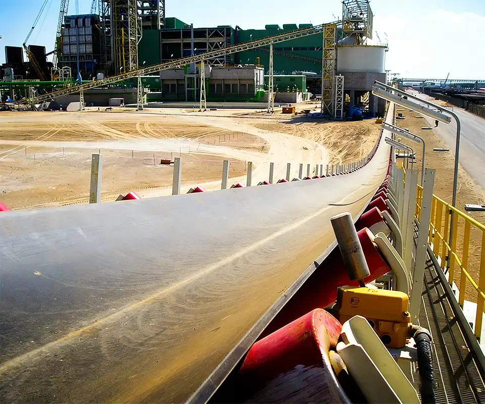
Horizontal curves are increasingly considered in overland conveyor routes serving copper mines, iron ore operations, coal mines, limestone quarries, and other large bulk-material handling projects. By following terrain and avoiding certain obstacles, a curved conveyor route may reduce the need for additional transfer stations, although its feasibility and economic benefits depend on the complete project design.
However, a conventional troughing idler arrangement that works reliably on a straight conveyor may not provide sufficient belt stability through a horizontal curve. The belt experiences a force toward the inside of the curve due to its longitudinal tension, and the idler arrangement must provide an appropriate balancing response.
Successful selection therefore requires more than choosing the correct roller diameter and trough angle. Engineers must consider horizontal curve radius, local belt tension, idler banking angle, trough geometry, roller load distribution, belt drift, idler spacing, bearing capacity, and installation accuracy.
Quick answer: Idlers for horizontal curves on mine overland conveyors should be selected using a calculated curve radius, local belt tensions, loaded and empty operating conditions, and the required belt tracking range. Engineered banking or other approved idler geometry may be necessary to counteract the lateral effects of belt tension. Carrying and return idlers must both be checked for stability, roller loading, bearing capacity, and installation tolerances. No universal banking angle, trough angle, or idler spacing is suitable for every horizontal curve.
Why Horizontal Curves Require Special Idler Design
On a straight belt conveyor, the main purpose of carrying idlers is to support the belt and conveyed material while maintaining the required trough profile. Properly aligned idlers also help the belt run centrally and minimize unnecessary resistance.
On a horizontal curve, the belt must continuously change its direction of travel. Because the belt is under longitudinal tension, this change in direction produces an inward radial force that tends to move the belt toward the center of the curve.
This inward tendency must be balanced by the effects of gravity, idler geometry, belt-to-roller friction, and other relevant forces. Properly designed idler banking can help maintain the belt within its allowable tracking position.
The challenge is that these forces change when belt tension, material load, operating speed, or environmental conditions change. A curve that tracks correctly at full production may behave differently when the belt runs empty or the conveyor accelerates.
Therefore, horizontal curve design must consider a range of operating conditions rather than only a single steady-state loading case.
1. Understand Horizontal Curve Radius
The horizontal curve radius describes how gradually the conveyor changes direction when viewed from above.
A large radius creates a gradual change in direction, while a smaller radius creates a tighter curve. For a given belt tension, a tighter curve generates a greater inward force per unit length.
The required radius depends on several factors, including belt width, longitudinal tension, carcass construction, trough angle, idler arrangement, available banking, and the allowable lateral displacement of the belt.
There is no universal minimum horizontal curve radius suitable for all mining conveyors. Some engineered overland conveyors can negotiate relatively tight curves, while other high-tension systems require substantially larger radii.
Before purchasing curved-section idlers, obtain the approved horizontal alignment drawing showing curve radius, direction, length, and the transition between straight and curved sections.
Selection principle: Do not choose a horizontal curve radius solely from belt width or a general idler catalogue. Curve feasibility should be confirmed through conveyor engineering analysis before idler banking angles and frame dimensions are finalized.
2. Calculate the Lateral Force Caused by Belt Tension
The inward force associated with a tensioned belt following a horizontal curve is a fundamental part of curved-conveyor design.
For an idealized belt under approximately constant local tension, the inward force per unit length can be estimated using:
q = T / R
q: Inward force per unit belt length (N/m); T: Local belt tension (N); R: Horizontal curve radius (m).
For example, consider a conveyor section with a local belt tension of 150 kN and a horizontal curve radius of 1500 m. The simplified inward force is approximately 100 N per meter of curved belt.
This is an illustrative calculation of the tension-related curvature force, not a complete prediction of belt drift or individual idler loading.
Actual analysis must include local changes in tension, gravitational effects, belt and material mass, operating speed, friction, idler geometry, and applicable dynamic conditions.
The key purchasing implication is that higher belt tension or a smaller curve radius generally increases the lateral-force demand that the idler system must accommodate.
3. Select Idler Banking Angles Through Engineering Analysis
Banking is one of the main methods used to help control belt position through horizontal curves.
In a banked idler arrangement, the complete idler set is inclined transversely relative to the nominal horizontal plane. This changes how gravity and contact forces act on the belt and material as the conveyor follows the curved route.
Banking should be distinguished from the trough angle. Trough angle describes the inclination of the wing rollers relative to the center roller, while banking describes the transverse inclination of the complete idler assembly.
The required banking orientation and magnitude depend on the curve direction, local tension, belt loading, and idler geometry. These should be clearly defined in the approved engineering drawings.
A banking angle that provides good tracking during full-load operation may not give the same result when the conveyor runs empty. As a result, engineers generally evaluate an acceptable range of banking angles across different loading and tension conditions rather than assuming one angle is ideal under every condition.
Important: Banking should be designed, not improvised during commissioning. Excessive or incorrectly oriented banking can create new tracking and roller-loading problems. The idler supplier should manufacture the curved-section frames according to the approved banking specifications.
4. Understand Trough Angle and Banking Angle Differences
Trough angle and banking angle influence belt behavior in different ways, so they should be stated separately in procurement documents.
| Design Parameter | Main Function | Procurement Consideration |
| Trough Angle | Forms the carrying-belt cross-section | Belt troughability, capacity, roller contact geometry |
| Banking Angle | Changes transverse orientation of the idler set through the curve | Curve radius, lateral force, belt drift, loading conditions |
| Roller Skew or Forward Tilt | Changes roller orientation relative to belt travel and can influence steering | Belt wear, additional resistance, approved adjustment limits |
Common carrying-idler trough angles include 20°, 30°, 35°, and 45°. However, the correct angle for a horizontal curve should be selected as part of the complete conveyor design.
Increasing trough angle may change the belt’s lateral behavior, but it also affects belt flexing, idler junction loads, and material-carrying geometry. A deeper trough is not automatically better for every curve.
For more information on conventional idler geometry, see the Conveyor Idler Types and Applications Guide.
5. Evaluate the Full Range of Belt Loading Conditions
One of the most common problems in horizontal curve design is selecting the idler arrangement only for full-load steady operation.
A mine overland conveyor may operate empty, partially loaded, fully loaded, or with uneven material distribution along its route. Belt tension and the forces available to stabilize the belt can change substantially between these conditions.
When the carrying belt is loaded, the weight of the conveyed material contributes to its behavior on the banked idlers. When the conveyor runs empty, that material weight is absent, potentially changing the balance of lateral forces.
Engineers should evaluate at least the following relevant conditions:
- Empty belt operation.
- Partial production loading.
- Normal and maximum material loading.
- Startup and acceleration.
- Normal deceleration and stopping.
- Emergency braking, where applicable.
- Changes in take-up tension.
- Relevant wet, dry, and contaminated belt conditions.
For each case, the selected banking and idler geometry should keep the belt within an acceptable tracking range while avoiding excessive local stresses.
6. Pay Special Attention to Empty Belt Tracking
Empty-belt tracking can be a critical condition for horizontally curved conveyors.
The belt may remain under substantial longitudinal tension even when no bulk material is being conveyed. Without the additional weight of the material, the gravitational forces contributing to belt stabilization are reduced.
As a result, the belt may drift farther toward the inside of the curve under certain empty-running conditions than during full-load operation.
This is one reason horizontal curve designs should not rely exclusively on full-load tracking observations or calculations.
The minimum belt weight, expected cover wear, tension distribution, and available idler contact forces should be considered where relevant to the approved design.
7. Select Carrying Idlers for Uneven Roller Loading
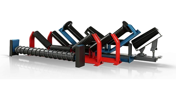
A three-roll troughing idler normally consists of one center roller and two wing rollers. On a straight, properly loaded conveyor, the load distribution depends primarily on the belt profile and material position.
Through a horizontal curve, lateral belt movement and banking can change how the belt presses against individual rollers.
The inside and outside wing rollers may therefore experience different contact loads. The magnitude and direction of the difference depend on the specific curve design and operating condition.
Do not assume that each wing roller carries an equal share of the load simply because the idler frame is based on a conventional three-roll configuration.
The selected rollers should have sufficient shell strength, shaft bending resistance, and bearing capacity for the maximum calculated individual roller loads.
Where roller loads are particularly demanding, the idler arrangement may require changes in diameter, bearing configuration, frame stiffness, or roller geometry.
8. Choose Suitable Return Idlers for Horizontal Curves
Return idlers deserve the same engineering attention as carrying idlers in a horizontally curved overland conveyor.
Although the return strand normally carries no bulk material, it remains under tension and must follow the conveyor’s curved route. Consequently, it also experiences lateral forces associated with belt curvature.
A flat return roller arrangement may not always provide sufficient lateral stability for a particular horizontal curve.
V-return idlers or specially configured multi-roll return idlers can be considered where their geometry helps the belt remain within the allowable tracking range.
Their actual suitability depends on belt width, return-side tension, curve radius, load distribution, and the available supporting geometry.
The return-side banking angle and idler configuration may differ from those used on the carrying side. These values should be calculated independently rather than copied directly from the loaded conveyor strand.
9. Determine Idler Spacing for the Horizontal Curve
Idler spacing influences belt sag, load distribution, contact geometry, operating resistance, and the number of rollers installed along the conveyor.
On a horizontal curve, the chosen spacing must also support the required belt path and lateral-force distribution.
Depending on the design, closer spacing may improve the continuity of belt support or help manage contact loads. However, it also increases roller quantity, installation work, operating resistance, and future maintenance requirements.
Importantly, the spacing used for a horizontal curve should not automatically be copied from guidance intended for vertical convex or concave curves. These arrangements involve different geometric and load considerations.
For the curved section, confirm idler spacing using the approved horizontal alignment and belt analysis, including roller loads, sag, belt contact, and tracking limits.
For general conveyor support-spacing considerations, see Conveyor Idler Spacing: How to Select the Right Distance.
10. Consider Belt Width, Stiffness and Troughability
Belt construction affects how the belt follows a horizontal curve and contacts the idler rollers.
The belt must have sufficient longitudinal strength to support the conveyor tension and suitable transverse flexibility to conform to the intended idler trough.
A relatively stiff belt may not distribute its contact load across the idler rolls in the same way as a more flexible belt. This can affect idler junction stresses, belt edge loading, and local contact conditions through the curve.
For high-tension steel cord belts, the horizontal curve design must also consider the distribution of longitudinal stress across the belt width and the belt’s ability to accommodate the curved path.
Before approving the idler arrangement, confirm the belt carcass type, tensile rating, thickness, transverse rigidity, and troughability requirements.
11. Check Belt Edge Stress and Idler Junction Loading
The belt’s longitudinal stress distribution can change as it follows a horizontal curve. The inner and outer portions of the belt follow different geometric paths, and the belt must accommodate this difference through its mechanical behavior.
Excessive local stresses may contribute to belt distortion, edge damage, or premature fatigue.
The junction between the center and wing rollers also deserves attention. Depending on belt stiffness, trough angle, and load distribution, excessive bending or contact pressure can occur near the junction region.
The engineering design should verify the belt’s allowable local stresses and ensure that the idler configuration provides suitable support throughout the curve.
A high-strength belt does not automatically eliminate these problems. Belt strength, flexibility, geometry, and support arrangement must be compatible.
12. Select Roller Diameter and Bearings for Curved Sections
Individual roller design remains important even when the overall idler arrangement is correctly engineered.
Roller diameter affects rotational speed, bearing requirements, shell construction, and rolling resistance. Shaft dimensions and bearing selection determine whether the roller can support the relevant operating loads.
For horizontal curves, bearings should be selected from the calculated load distribution rather than an assumed equal load on every roller.
Poor idler alignment or unintended roller skew can create additional contact effects and wear that are not represented by the basic vertical loading calculation.
For long-distance conveyors containing many idlers, rotational resistance can also influence total belt tension and energy consumption. Low-resistance roller construction may be worth considering where the performance benefit is supported by appropriate testing and compatible mechanical design.
The final specification should consider roller diameter, shell thickness, shaft deflection, bearing life, seal drag, rotational resistance, runout, and operating speed.
13. Steel, HDPE and Other Roller Materials
Roller material selection for horizontal curves should account for mechanical loading, operating resistance, environmental exposure, maintenance, and total operating cost.
| Roller Construction | Potential Advantage | Selection Concern |
| Steel Roller | High stiffness and established heavy-duty construction | Weight, corrosion, bearing protection, rolling resistance |
| Engineered HDPE Roller | Low shell weight and resistance to metallic shell corrosion | Load rating, temperature, deformation, internal reinforcement |
| Composite or Reinforced Roller | Potential balance of weight, stiffness, and environmental performance | Verified structural performance and long-term durability |
| Protected Steel Roller | Heavy-duty steel structure with added corrosion protection | Coating damage, maintenance, shaft and bearing corrosion |
HDPE or composite rollers should not automatically be assumed to have the same load capacity as steel rollers of identical external dimensions.
Likewise, heavier steel rollers are not automatically the most reliable choice for every overland application. The selected construction should meet the actual loading, speed, environmental, and maintenance requirements.
14. Installation Accuracy Is Critical in Horizontal Curves
Even correctly designed curved-section idlers can perform poorly if they are installed inaccurately.
On straight conveyors, misalignment can introduce unwanted belt steering. On horizontal curves, these errors can interfere with the intended balance of lateral forces and cause excessive belt drift or uneven roller loading.
Important installation checks include the idler centerline position, mounting elevation, banking angle, trough angle, roller-axis orientation, structural alignment, and spacing between consecutive idler sets.
Idler frames should be positioned according to the approved curved alignment, not simply aligned along a straight chord between distant structural reference points.
The installation should also account for the gradual transition in banking angle between straight and curved sections.
A small mounting error repeated across many idler sets can produce significant tracking and wear problems over a long horizontal curve.
15. Design Curved-Section Idler Frames for Accurate Installation
The idler frame determines the relative positions of the rollers and their installation interfaces with the conveyor structure.
For a horizontal curve, the frame may require a defined banking orientation, special mounting brackets, adjustable supports, or other project-specific construction features.
Frame strength is also important because uneven roller forces can create loading conditions that differ from those of a conventional straight-section frame.
Procurement drawings should identify mounting-hole center distances, support elevations, roller positions, trough geometry, banking direction, frame orientation, and required installation clearances.
If frames are supplied for several curves, they should be identified by installation location and orientation to prevent incorrect placement.
Replacement frames should also be checked for compatibility with the existing roller shaft ends, bearing interfaces, and conveyor structure.
16. Avoid Using Side Guide Rollers as the Main Curve-Control Method
Some curved conveyor designs include side guide or restraining rollers to limit exceptional belt movement.
These devices may provide protection against excessive drift under specified operating conditions, but they should not be treated as a substitute for adequate curve geometry and properly engineered banking.
Continuous belt-edge contact with guide rollers can produce additional friction, edge wear, bearing loads, and maintenance requirements.
Where restraining rollers are included, their spacing, position, allowable contact force, and clearance should be established through the conveyor design.
Persistent belt drift should be investigated through tension analysis, banking verification, idler alignment, loading conditions, and belt behavior rather than corrected only by increasing guide-roller contact.
17. Pay Attention to Combined Horizontal and Vertical Curves
Mine overland conveyors often follow natural terrain, and a horizontal curve may coincide with a change in elevation.
When horizontal and vertical curvature occur together, the idler system may experience a combination of lateral and vertical force effects.
Convex vertical curves can change idler contact forces and local belt stress. Concave vertical curves may introduce belt lift-off concerns under certain tension and loading conditions.
These effects can influence the belt’s ability to remain properly supported and centered through the horizontal curve.
The combined geometry should therefore be evaluated through suitable three-dimensional conveyor design and dynamic analysis rather than treating the horizontal and vertical curves as unrelated features.
18. Consider Changes in Curve Direction and Transition Geometry
Some overland conveyors contain several horizontal curves, including sections that turn in opposite directions.
A left-hand curve and a right-hand curve may require different banking orientations. Where the route changes from one curve direction to another, the transverse idler geometry must transition appropriately.
Abrupt changes in banking or support elevation can introduce unwanted belt twisting, uneven contact, and tracking disturbances.
The approved drawings should therefore identify the beginning and end of each curve, banking transitions, idler orientation, and any special frames required between different sections.
19. Inspect Horizontal Curve Idlers During Commissioning
Commissioning is an important stage for confirming that the installed idler system performs according to the approved design.
The commissioning program should evaluate belt behavior under representative empty, partially loaded, and loaded conditions, where these can be tested safely and are relevant to the operating requirements.
Inspection should include belt drift, edge clearance, roller contact, abnormal noise, vibration, tracking consistency, and any evidence of uneven wear.
For long curves, recording belt position at defined locations can help identify whether tracking changes gradually or only near particular idler frames.
If a tracking problem occurs, review the approved geometry and actual operating conditions before making adjustments. Uncontrolled changes to banking or roller skew can produce additional problems elsewhere in the curve.
20. Common Problems in Curved Overland Conveyor Idlers
| Observed Problem | Possible Cause | Recommended Investigation |
| Belt Drifts Toward Inside of Curve | Insufficient stabilizing forces, high local tension, incorrect geometry | Verify curve radius, banking, tension and loading cases |
| Excessive Drift in Opposite Direction | Unsuitable banking or unintended steering effects | Check frame orientation, idler alignment, operating conditions |
| Uneven Wing Roller Wear | Unequal contact loads or unintended roller skew | Review roller loads, banking, bearing and shell condition |
| Belt Edge Damage | Excessive drift, continuous guide contact, abnormal local stress | Check belt position, guide clearance, curve stress analysis |
| Frequent Bearing Failures | High roller loads, misalignment, contamination | Verify loads, bearing rating, seals and installation geometry |
| Tracking Changes Between Empty and Full Load | Different gravity and tension conditions | Review full operating envelope and banking design |
These symptoms are diagnostic indicators rather than definitive root causes. The final diagnosis should be supported by operating data, site measurements, and engineering review.
21. What Information Should Be Included in the RFQ?
A detailed request for quotation helps the manufacturer provide curved-section idlers that match the approved conveyor design.
| RFQ Category | Required Information |
| Conveyor Route | Horizontal alignment, curve radius, curve length, direction, vertical profile |
| Belt Specification | Width, speed, carcass type, tensile rating, thickness, transverse stiffness |
| Operating Conditions | Material type, bulk density, throughput, loading range, operating schedule |
| Belt Tension | Local carrying and return tensions, startup, stopping and applicable transients |
| Curve Geometry | Approved trough angles, banking angles, transition geometry, allowable drift |
| Idler Arrangement | Carrying or return, number of rolls, idler spacing, calculated roller loads |
| Roller Dimensions | Diameter, shell length, shaft dimensions, mounting interfaces |
| Roller Construction | Shell material, bearings, sealing, runout, rotational resistance requirements |
| Frame Design | Mounting dimensions, banking orientation, frame strength, adjustment provisions |
| Quality Requirements | Material verification, dimensional checks, assembly inspection, test requirements |
| Commercial Details | Quantity by curve location, drawings, packaging, delivery date, destination |
22. Practical Procurement Checklist for Horizontally Curved Idlers
01. Obtain the approved horizontal curve layout and radius.
02. Confirm local belt tensions for all relevant operating cases.
03. Evaluate belt drift during empty and loaded operation.
04. Use engineering-approved banking angles and orientations.
05. Confirm the trough angle and belt troughability.
06. Check the individual center and wing roller load requirements.
07. Select suitable carrying and return idler arrangements.
08. Verify idler spacing, roller diameter, shaft strength, and bearings.
09. Check belt edge stress and idler junction loading.
10. Review the interaction between horizontal and vertical curves.
11. Confirm frame mounting geometry and installation tolerances.
12. Identify left-hand, right-hand, and transition frames separately.
13. Agree on inspection and quality-control requirements before production.
14. Include tracking verification in the conveyor commissioning plan.
23. Common Mistakes When Selecting Idlers for Horizontal Curves
Mistake 1: Using Straight-Section Idlers Without Reviewing the Curve
Conventional idlers may not provide the required banking, contact geometry, or load capacity for a horizontal curve.
Mistake 2: Selecting One Banking Angle from Full-Load Operation
The belt may behave differently when running empty or during acceleration and deceleration. The full operating envelope must be considered.
Mistake 3: Ignoring Return-Side Curvature
The return strand also follows the horizontal curve and can experience significant lateral forces because of belt tension.
Mistake 4: Assuming Equal Wing Roller Loads
Banking and belt displacement can produce unequal roller loads. Bearings and shafts must be selected for the actual maximum individual loads.
Mistake 5: Correcting Persistent Drift Only with Guide Rollers
Continuous belt-edge restraint can increase wear. The underlying curve geometry, loading, and alignment should be evaluated.
Mistake 6: Ignoring Installation Accuracy
Incorrect banking direction, frame position, or roller alignment can undermine an otherwise suitable curve design.
Mistake 7: Treating Horizontal and Vertical Curves as Identical
Horizontal curves primarily introduce lateral path-following requirements, while vertical curves introduce different support and belt-stress effects. Combined curves require integrated evaluation.
How to Compare Idler Suppliers for Curved Mine Overland Conveyors
For horizontally curved conveyors, suppliers should be evaluated according to their ability to manufacture idler assemblies that match detailed engineering drawings and project-specific operating requirements.
Important purchasing considerations include frame dimensional accuracy, correct banking orientation, roller specifications, bearing capacity, sealing quality, structural fabrication, welding consistency, and inspection documentation.
For large overland installations, consistent manufacturing quality is particularly valuable because a curve may contain many closely coordinated idler assemblies. Small dimensional variations across multiple frames can affect installation and belt behavior.
Ask suppliers to confirm whether they can manufacture different frame orientations, banking configurations, mounting dimensions, and roller arrangements according to the approved project drawings.
The conveyor designer should establish the required horizontal curve geometry, banking, loads, and allowable belt movement. The idler manufacturer should then verify that the supplied components satisfy those mechanical and dimensional requirements.
Custom Conveyor Idlers for Mine Overland Conveyors from SHENGYUAN
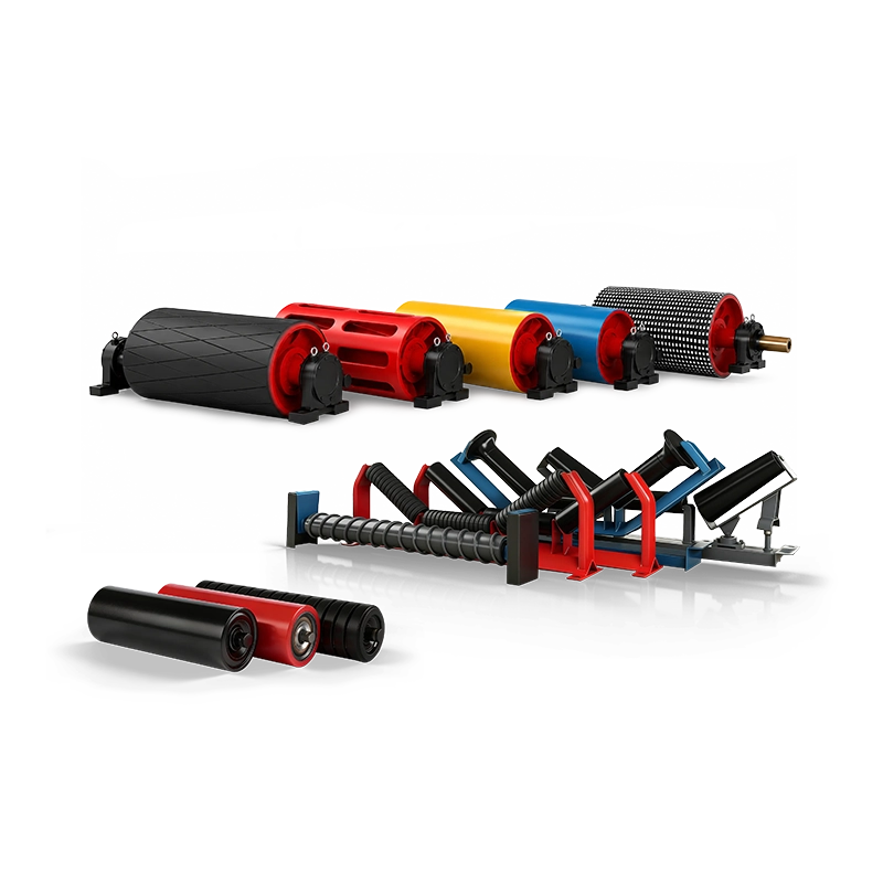
SHENGYUAN supplies conveyor rollers, idlers, frames, pulleys, belts, cleaners, and related components for mining, quarrying, coal handling, cement plants, ports, power stations, and other heavy-duty bulk-material handling applications.
The SWCONS conveyor roller range includes carrying rollers, return rollers, impact rollers, steel rollers, HDPE rollers, and other configurations for different conveyor operating conditions.
For horizontally curved mine overland conveyors, custom roller and idler-frame requirements can be coordinated according to approved trough angles, banking geometry, roller dimensions, shaft interfaces, bearing specifications, frame construction, and installation drawings.
Through custom conveyor solutions, idler and frame manufacturing can be coordinated with customer-provided dimensional drawings and mechanical requirements.
For replacement projects, existing frame drawings, mounting dimensions, roller specifications, and installation-position records are particularly useful for confirming interchangeability and avoiding installation problems.
Need custom idlers for a horizontally curved mine overland conveyor?
Send the approved conveyor alignment, curve radius, belt width, belt speed, local belt tensions, required trough and banking angles, carrying and return idler configurations, idler spacing, calculated roller loads, shaft and bearing specifications, mounting drawings, and required quantities. These details help establish an accurate manufacturing specification for the curved-section idlers and frames.
Conclusion: Idler Geometry and Belt Tension Must Be Designed Together
Horizontal curves can provide useful routing flexibility for long-distance mine overland conveyors, but their successful operation depends on accurate engineering and carefully selected idler arrangements.
The inward force created by belt tension must be balanced by suitable belt support, banking geometry, and contact conditions. These relationships vary with curve radius, local belt tension, material loading, and operating state.
Carrying and return idlers should both be evaluated. Roller loads, belt edge stresses, idler spacing, bearing capacity, frame geometry, and installation accuracy also influence performance.
The most reliable procurement approach is to use approved curve calculations and dimensional drawings, clearly specify different idler configurations, and verify that manufacturing and installation match the intended geometry.
The best idler arrangement for a horizontal mine conveyor curve is not simply a stronger conventional idler or one installed at a greater angle. It is a complete support system whose trough geometry, banking, load capacity, roller construction, and installation accuracy keep the belt stable across the full range of operating conditions.
FAQ: Idlers for Horizontal Curves on Mine Overland Conveyors
“`