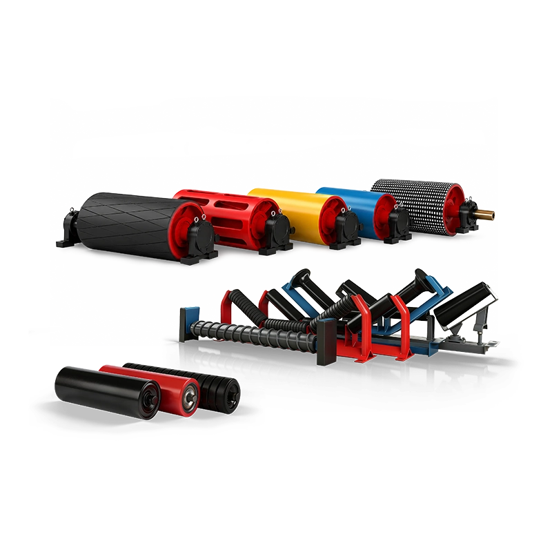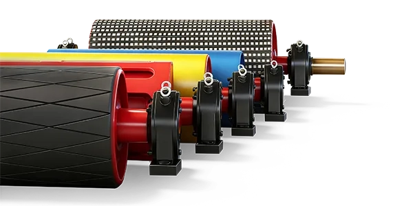
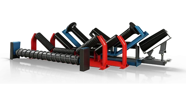




Conveyor idler spacing is one of the basic design parameters of a belt conveyor, but it should not be treated as a fixed dimension that can be copied from one conveyor to another. The distance between idler sets affects belt sag, load distribution, roller loading, impact protection, belt stability, operating resistance, and the total number of rollers required throughout the conveyor.
For mining, quarrying, cement, coal handling, aggregates, ports, steel plants, and power stations, different conveyor sections normally require different idler spacing. Carrying idlers, return idlers, impact idlers, and idlers installed through convex or concave curves should not automatically use the same spacing.
As a practical engineering reference, carrying idlers are commonly arranged at approximately 1000–1200 mm, impact idlers at approximately 300 or 500 mm, return idlers at approximately 3000 mm, carrying-side idlers through curved sections at approximately 500 or 600 mm, and return-side idlers through curved sections at approximately 1500 mm. These values are starting references rather than universal requirements.
Quick answer: Conveyor idler spacing should be selected according to the idler position and operating duty. Normal carrying idlers commonly use 1000–1200 mm spacing, return idlers about 3000 mm, impact idlers about 300–500 mm, carrying idlers in convex or concave curves about 500–600 mm, and return idlers in curved sections about 1500 mm. Material bulk density, lump size, and loading drop height should be considered before finalizing the arrangement.
Why Does Conveyor Idler Spacing Matter?
Idlers support the conveyor belt and the material carried on it. If the distance between supporting points becomes too large, the belt can sag excessively between idler sets. This changes the belt profile and may make material containment less stable.
Closer spacing provides more frequent support and distributes load across more idler sets. However, installing more idlers than necessary also increases equipment quantity, installation work, spare-parts requirements, and the number of rotating components that must be maintained.
The objective is therefore not to minimize spacing as much as possible. The objective is to provide sufficient belt support for each conveyor section without unnecessary component cost.
Typical Conveyor Idler Spacing at a Glance
| Conveyor Position | Typical Reference Spacing | Main Purpose |
| Normal carrying side | 1000–1200 mm | Support loaded belt and material |
| Impact/loading zone | 300 or 500 mm | Increase support and absorb loading impact |
| Carrying-side convex/concave curve | 500 or 600 mm | Provide closer support through changing geometry |
| Normal return side | About 3000 mm | Support empty return belt |
| Return-side convex/concave curve | About 1500 mm | Improve support through curved sections |
These dimensions are useful for preliminary selection and quotation discussions. Final engineering should verify the actual material, conveyor arrangement, belt characteristics, loading conditions, and project requirements.
1. Carrying Idler Spacing: Typically 1000–1200 mm
Carrying idlers support both the conveyor belt and the bulk material. Because the loaded carrying side experiences much greater weight than the empty return side, carrying idlers are normally installed considerably closer together.
A practical reference for general carrying-side applications is approximately 1000–1200 mm between idler sets. This range is commonly suitable as an initial layout value for conventional bulk material conveyors.
However, the spacing should become more conservative as the conveyor duty becomes heavier. Dense material increases the load supported by each idler set, while large lumps can create additional dynamic loads as material moves along the belt.
Beyond these practical reference ranges, final engineering commonly also reviews belt width, belt tension, belt speed, roller diameter, shaft strength, bearing capacity, allowable belt sag, and conveyor geometry.
Selection principle: Do not increase carrying-idler spacing simply to reduce roller quantity. The belt and idler set must still provide stable support for the actual material load.
2. Why Impact Idlers Need Much Closer Spacing
The loading zone operates under completely different conditions from the normal carrying run. Material falling from a hopper, feeder, crusher, or transfer chute can generate concentrated impact when it strikes the conveyor belt.
For this reason, impact idlers and conveyor rollers are normally installed more closely together under the receiving chute. A practical reference spacing is approximately 300 or 500 mm.
Closer spacing means that more idler sets support the belt beneath the loading zone. This helps distribute the impact load and reduces the unsupported belt length between adjacent idlers.
When Should You Consider 300 mm Instead of 500 mm?
The exact choice should be based on loading severity rather than on one fixed rule. Where material has greater bulk density, larger lumps, or a higher drop height, the receiving section experiences more demanding impact conditions and may require closer support.
A lower-impact receiving point may not require the same arrangement as a crusher discharge handling large pieces of dense rock. This is why material bulk density, lump size, and drop height should always be provided when selecting impact idler spacing.
Important: The impact-zone spacing should be selected together with the impact roller construction and loading chute design. More rollers cannot fully compensate for an uncontrolled transfer point with excessive drop height or poor material direction.
3. Why Return Idlers Can Be Spaced Farther Apart
After material is discharged, the empty conveyor belt returns toward the tail pulley. Because the return idlers support primarily the belt rather than the full material load, they can usually be installed at greater intervals than carrying idlers.
A typical reference spacing for normal return idlers is approximately 3000 mm.
This does not mean return-side design is unimportant. Excessive spacing can increase return-belt sag, while sticky carryback can accumulate on return rollers and affect belt stability. Wider belts may also use V-return arrangements to improve return-side centring.
4. Idler Spacing Through Convex and Concave Curves
Curved conveyor sections require special attention because the belt is changing its vertical profile instead of travelling along a simple straight line.
On the carrying side, a practical reference for convex or concave curved sections is approximately 500 or 600 mm. This is significantly closer than the 1000–1200 mm spacing used on many normal straight carrying sections.
On the return side, curved sections may use approximately 1500 mm spacing compared with about 3000 mm on a normal straight return run.
The reason for closer support is that belt geometry and contact conditions change through curves. The belt should remain properly supported as it follows the designed conveyor profile.
| Section | Straight Section | Curved Section |
| Carrying side | 1000–1200 mm | 500 or 600 mm |
| Return side | About 3000 mm | About 1500 mm |
5. Transition Idlers Near the Head Pulley
Idler layout is not only about distance. The type and angle of the idler also change near terminal pulleys.
A practical arrangement near the head pulley is to use a 10° transition idler as the first idler set and a 20° transition idler as the second set before the belt reaches its normal troughing arrangement.
Transition idlers allow the belt to move gradually between the flat pulley profile and the normal troughed carrying profile. This helps reduce sudden changes in belt shape and excessive edge tension.
For wider, higher-tension, or specialized belts, the complete transition distance should be checked for the actual belt construction and pulley arrangement rather than relying only on two standard idler positions.
6. How Often Should Self-Aligning Idlers Be Installed?
Self-aligning idlers are not normally installed at every carrying position. Their purpose is to provide periodic belt-centering assistance where required.
A practical arrangement is to include approximately one upper self-aligning idler set for every ten upper carrying idler sets. On the return side, approximately one lower self-aligning set for every six flat return idler sets can be used as a reference arrangement.
These self-aligning idlers should assist a correctly aligned conveyor. They should not be used to compensate for severe off-centre loading, pulley misalignment, structural distortion, or material buildup.
7. Where Should Spiral Return Rollers Be Installed?
Spiral return rollers are used where carryback remains attached to the return side of the belt. Their helical surface helps reduce material buildup and improves return-belt cleanliness.
A practical layout is to install three consecutive spiral roller sets on the return belt near the head section, where carryback is most likely to remain immediately after material discharge.
They should be considered part of the belt-cleaning strategy rather than a replacement for properly selected primary and secondary belt cleaners.
How Material Characteristics Affect Idler Spacing
Bulk Density
Higher bulk density means more material mass is carried over a given conveyor length. This increases the load supported by carrying idlers and should be considered before using the wider end of a spacing range.
Maximum Lump Size
Large lumps introduce more concentrated and dynamic loading. This is particularly important in receiving zones, where large pieces can strike the belt directly above or between adjacent idler sets.
Drop Height
Greater drop height increases the severity of material impact at the loading point. As loading becomes more severe, the impact idler arrangement should be reviewed rather than automatically applying a standard spacing.
Three important inputs: Material bulk density, maximum lump size, and drop height should always be provided when evaluating idler spacing, particularly around loading and impact zones.
Should Wider Belts Automatically Use Closer Idler Spacing?
Not automatically. Belt width is important, but spacing should not be determined from belt width alone.
A wide belt carrying lightweight material may create a different idler load from a narrower belt carrying dense ore. Likewise, two identical belt widths may require different loading-zone spacing because one receives fine material from a small drop height while the other receives large rocks from a crusher chute.
For final selection, the reference spacing should therefore be checked against the actual material, conveyor load, belt condition, and system geometry.
Common Idler Spacing Selection Mistakes
Mistake 1: Using One Spacing Throughout the Entire Conveyor
Straight carrying sections, loading zones, curves, and return sections have different support requirements. Using one dimension throughout the conveyor ignores these operating differences.
Mistake 2: Using 1000–1200 mm Under a Severe Loading Chute
Normal carrying-idler spacing should not automatically continue through a high-impact receiving point. Impact zones typically require substantially closer support, such as approximately 300 or 500 mm.
Mistake 3: Increasing Spacing Only to Reduce Purchase Cost
Fewer idlers reduce initial component quantity, but spacing that is too large can create excessive belt sag and greater load on each remaining idler set. Initial savings should therefore be evaluated against conveyor reliability and belt support.
Mistake 4: Ignoring Curved Conveyor Sections
Curved sections normally require closer support than straight conveyor runs. Carrying-side curved sections may use approximately 500–600 mm spacing, while return-side curved sections may use around 1500 mm as a practical reference.
A Practical Step-by-Step Idler Spacing Selection Method
01. Divide the conveyor into carrying, loading, curved, transition, and return sections.
02. Use approximately 1000–1200 mm as an initial carrying-idler reference.
03. Use approximately 300 or 500 mm as an initial impact-zone reference.
04. Use approximately 500 or 600 mm through carrying-side curved sections.
05. Use approximately 3000 mm as an initial normal return-idler reference.
06. Reduce return spacing to about 1500 mm through curved sections.
07. Confirm material bulk density, maximum lump size, and loading drop height.
08. Check transition and self-aligning idler positions.
09. Review belt sag, belt tension, idler load, and conveyor geometry during final engineering.
10. Confirm the complete layout before manufacturing frames and supporting structures.
What Information Should You Provide When Ordering Idlers?
When requesting a quotation, providing only the belt width is usually not enough for an accurate heavy-duty idler recommendation.
Provide: belt width and belt speed;
conveyor capacity and material type;
material bulk density and maximum lump size;
drop height and loading conditions;
idler type and trough angle;
existing idler spacing;
roller diameter, roller length, and shaft dimensions;
frame and mounting dimensions;
conveyor layout drawings and required quantity.
Why Choose SHENGYUAN for Conveyor Idlers and Rollers?
SHENGYUAN supplies conveyor rollers, idlers, pulleys, belts, and related components for heavy-duty bulk material handling applications, including mining, quarrying, aggregates, cement, coal handling, ports, steel plants, and power stations.
Different conveyor sections can require troughing idlers, impact idlers, transition idlers, self-aligning idlers, return idlers, V-return idlers, or spiral rollers. Coordinating idler type with spacing can help create a more appropriate support arrangement than purchasing individual rollers without considering their installation position.
Through custom conveyor solutions, roller diameter, face length, shaft ends, bearings, sealing arrangements, trough angles, frame dimensions, and mounting configurations can be manufactured according to customer drawings and conveyor requirements.
For replacement projects, existing drawings are particularly useful because the roller itself and the idler-frame installation dimensions must both match the conveyor structure. Idlers can also be coordinated with conveyor pulleys and other components for consolidated project or spare-parts sourcing.
Need to confirm idler spacing for a project?
Provide the conveyor layout, belt width, belt speed, capacity, material, bulk density, maximum lump size, drop height, trough angle, idler type, existing spacing, curve locations, roller dimensions, and drawings. The complete conveyor layout should be reviewed before finalizing idler quantities and frame positions.
Conclusion: Idler Spacing Should Change with Conveyor Duty
Conveyor idler spacing should not be one fixed dimension from head to tail. Normal carrying sections can use approximately 1000–1200 mm as a practical reference, while impact zones require much closer support at around 300 or 500 mm.
Return idlers may be arranged at approximately 3000 mm because they support the empty belt. Curved sections require closer support, with carrying-side spacing around 500 or 600 mm and return-side spacing around 1500 mm as useful reference values.
Material bulk density, lump size, and loading drop height should then be used to judge whether the preliminary arrangement needs adjustment. Additional engineering checks can include belt sag, belt tension, speed, idler load, belt width, curve geometry, and loading-zone conditions.
The correct approach is not to ask for one universal idler spacing. Divide the conveyor into different operating zones, choose the appropriate idler type and reference spacing for each zone, and then verify the arrangement against the actual conveyor duty.