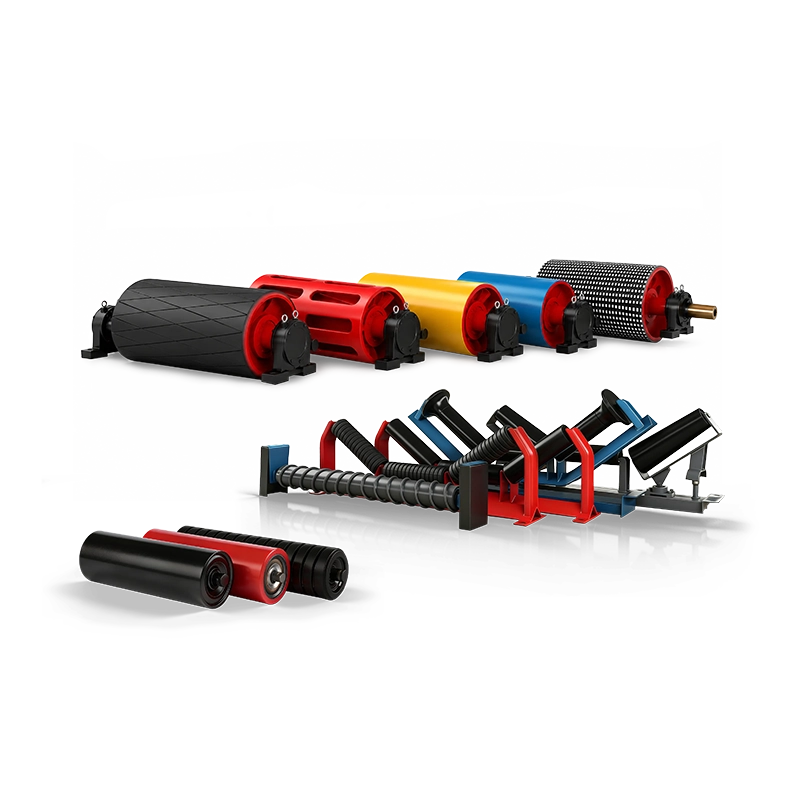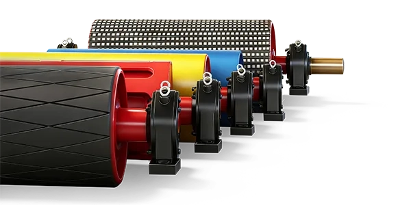
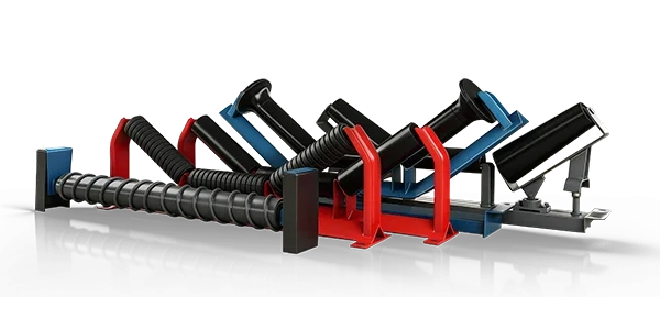
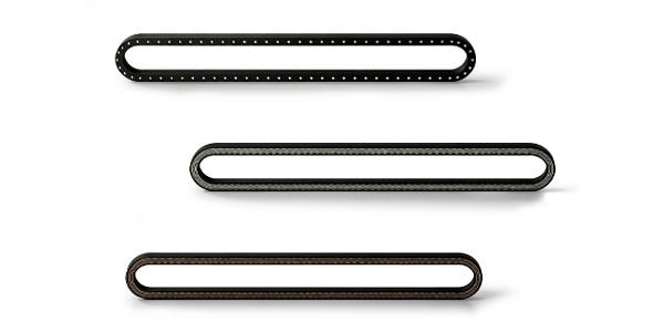



Planning conveyor components for a cement kiln feed line is not only a matter of selecting a belt, several idlers, and a set of pulleys. The reliability of the system depends heavily on the interfaces between those components. Belt width affects pulley face width and idler geometry. Belt construction affects minimum pulley diameter. Loading-zone geometry affects impact-idler spacing. Take-up travel affects pulley position and belt tension. Cleaner installation depends on head-pulley geometry and available chute space.
These interfaces become particularly important in cement plants because conveyors can operate around abrasive limestone, raw materials, coal, additives, cement dust, and elevated ambient temperatures. Fine dust can enter bearings and seals, while material buildup can change pulley and roller surfaces. A component that is individually suitable can still perform poorly if it does not match the surrounding equipment.
For a new kiln-feed or related cement-process conveyor section, the best approach is to define the complete conveying duty first, then coordinate belt dimensions, idler geometry, pulley interfaces, take-up travel, chute positions, cleaner clearance, bearing centers, structural mounting points, and maintenance access before manufacturing begins.
Quick answer: Plan conveyor interfaces from one controlled layout drawing. Confirm belt width and construction first, then coordinate idler trough angle and spacing, pulley diameter and face width, shaft and bearing positions, take-up travel, chute width, cleaner installation space, and frame mounting dimensions. Every supplier should work from the same belt line, centerline, operating load, and interface dimensions.
Why Conveyor Interfaces Matter in Cement Plants
A belt conveyor functions as a connected mechanical system. The belt passes continuously over idlers and pulleys while interacting with loading chutes, skirt boards, cleaners, take-up equipment, guards, and the drive system.
If one interface is wrong, the effect can appear elsewhere. An incorrect pulley diameter may increase belt flexing stress. A frame installed at the wrong height may disturb the belt line. A chute positioned too close to a pulley may leave insufficient transition distance. A cleaner installed without enough clearance can interfere with the discharge chute.
This is why component interfaces should be finalized before purchase orders are split among multiple manufacturers.
For an overview of how the major components work together, see the Belt Conveyor Components Guide.
1. Start with One Conveyor Design Basis
All component suppliers should receive the same basic operating information. Conflicting assumptions are a common source of interface problems.
The design basis should include:
material type and condition;
bulk density;
maximum lump size where applicable;
normal and peak capacity;
conveyor length and lift;
belt width and speed;
operating temperature;
dust and moisture conditions;
required operating hours and maintenance philosophy.
Once these values are controlled, belt, idler, pulley, chute, and take-up selections can be developed from the same operating duty.
2. Coordinate Belt Width with Idlers and Pulleys
Belt width influences several interfaces immediately. Idler roller lengths, frame width, pulley face width, chute width, skirt-board clearance, and structural spacing all depend on it.
Do not allow one supplier to select a nominal belt width while another designs pulleys from a different assumption. The approved width should be shown on the general arrangement drawing and repeated on all relevant component specifications.
The pulley face should provide suitable belt-edge clearance, while idler roller arrangement should support the intended belt profile without leaving unsupported areas near the edges.
3. Match Belt Construction to Pulley Diameter
Belt construction affects how tightly the belt can bend around a pulley. A stronger, thicker, or stiffer belt may require larger pulleys than a lighter fabric belt.
Drive, tail, bend, snub, and take-up pulley diameters should therefore be checked against the final belt carcass and cover construction before manufacturing.
Changing the belt specification late in the project without rechecking the pulleys can create excessive flexing stress, splice problems, or reduced belt life.
For more detail on pulley functions and selection, see the Conveyor Pulleys Guide.
4. Coordinate Trough Angle and Transition Length
The belt is generally flat on the pulley and troughed through the normal carrying section. Transition idlers gradually change the belt from one profile to the other.
Common carrying trough angles include 20°, 30°, 35°, and 45°, with 35° widely used in many bulk-material applications. Whatever angle is selected, the transition zone must provide enough distance for the belt to change shape without excessive edge or center stress.
The final transition arrangement depends on belt width, carcass stiffness, tension, pulley position, and trough angle. The pulley supplier and idler-frame supplier should therefore work from the same belt centerline and transition layout.
5. Define Idler Zones Before Finalizing the Frame Layout
A cement conveyor should normally be divided into functional zones rather than using one idler arrangement throughout.
| Conveyor Zone | Typical Idler Requirement |
| Loading Zone | Impact idlers or suitable impact support |
| Normal Carrying Section | Troughing carrying idlers |
| Pulley Transition | Transition idlers |
| Return Strand | Flat or V-return idlers |
| Tracking Locations | Selected self-aligning idlers where required |
Defining these zones early helps prevent conflicts between chute length, impact-idler spacing, transition length, cleaners, and structural supports.
6. Coordinate the Loading Chute with Impact Support
The chute should discharge material onto a section of belt that is properly supported for the expected impact.
If the loading point is positioned between widely spaced idlers, the belt can deflect sharply under material impact. This can damage the belt and make skirt sealing difficult.
Impact idlers are therefore normally spaced more closely than standard carrying idlers. Practical references such as 300 mm or 500 mm are commonly used for loading zones, while normal carrying spacing may be around 1000–1200 mm. Final spacing should still reflect actual material, drop height, and belt duty.
7. Match Skirt-Board Width to the Belt and Idler Profile
The skirt system should contain the incoming material without pushing it too close to the belt edges.
As a practical starting reference, guide-chute bottom width is often approximately one-half to two-thirds of belt width, but final dimensions depend on capacity, lump size, trough angle, material flow, and sealing arrangement.
The skirt-board designer should therefore use the actual idler trough geometry rather than a generic flat-belt cross-section.
For detailed loading-zone guidance, see Conveyor Skirt Board and Chute Design.
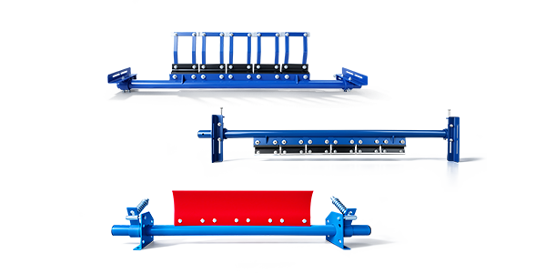
8. Coordinate Head Pulley, Cleaner and Discharge Chute
The head pulley area is one of the most crowded interface zones in a conveyor. The drive or head pulley, cleaner, chute, bearing housings, guards, and structural supports may all compete for space.
The primary cleaner should be positioned so removed material falls into the discharge chute rather than onto the floor or return belt.
At the same time, there must be enough clearance for cleaner adjustment and blade replacement. Maintenance personnel should not need to remove major chute sections simply to change a wear component.
Interface check: Finalize the head-pulley centerline, cleaner mounting position, chute wall, bearing housing, and maintenance access on the same drawing.
9. Plan Tail Pulley Protection from Carryback
Fine cement-plant material and dust can travel back on the return side of the belt. If loose material reaches the tail pulley, it can become trapped between the pulley and belt.
This can create buildup, tracking problems, local belt stress, and contamination around the tail area.
Return-side or empty-section cleaning should therefore be coordinated with the tail and take-up pulley positions. The cleaner must have enough installation space while remaining accessible for inspection.
10. Define Take-Up Travel Before Structural Fabrication
The take-up system maintains belt tension and accommodates belt-length changes during operation.
Screw, gravity, trolley, and winch systems require different amounts of space and structural support. Take-up pulley travel must therefore be defined before surrounding steelwork is finalized.
A common interface mistake is designing the pulley correctly but leaving insufficient travel, maintenance clearance, or counterweight movement.
Take-up travel, belt tension, pulley shaft loading, guards, access platforms, and limit positions should be reviewed together.
11. Coordinate Pulley Shafts with Bearings and Structures
Pulley drawings should show more than shell diameter and face width. Bearing-center distance, shaft steps, coupling extension, non-drive-side extension, keyways, locking assemblies, and shoulders must match the bearing housings and surrounding structure.
The conveyor structure supplier should use the approved bearing-center dimensions rather than estimating support positions from pulley face width.
For drive pulleys, coupling and gearbox interfaces should be included in the same review because even a small shaft-extension mismatch can delay installation.
12. Make Bearing and Seal Selection Consistent with Cement Dust
Cement plants can expose rollers and pulleys to very fine dust. Dust entering bearings can contaminate lubricant and accelerate wear.
Idler and pulley bearing arrangements should therefore be selected together with suitable sealing and maintenance practices.
Where washdown, outdoor moisture, or elevated temperature also occur, these conditions should be included in the same component specification rather than treated separately.
13. Plan for Thermal Conditions Around the Kiln Area
Even where the conveyed material itself is not extremely hot, ambient conditions around a kiln-related process area can be higher than those in an open quarry conveyor.
Belt compound, rubber lagging, seals, grease, cleaners, and nearby structural components should therefore be checked against the expected operating temperature.
If hot material can occasionally enter the conveyor, provide both normal and peak material temperatures and their duration rather than supplying only one maximum value.
14. Coordinate Belt Tracking Interfaces
Tracking performance is influenced by more than self-aligning idlers. Pulley alignment, frame squareness, idler installation, loading direction, belt tension, and material buildup all affect the belt path.
A belt loaded off-center may mistrack even when all mechanical components are correctly manufactured. Likewise, a correctly centered load can still be disturbed by a misaligned tail or bend pulley.
The design should therefore define pulley centerlines, idler-frame references, chute centerline, and conveyor structural centerline from one common coordinate system.
15. Leave Enough Space for Maintenance
A component interface is not complete if the equipment fits during installation but cannot be maintained afterward.
Provide sufficient access to remove rollers, withdraw pulley bearings, replace cleaner blades, inspect lagging, adjust take-up equipment, and service guards.
Maintenance clearances should be shown on layout drawings before platforms, handrails, chute walls, and nearby equipment are finalized.
16. Standardize Interfaces Where Practical
A new cement line provides an opportunity to reduce future spare-parts complexity.
Where mechanical duty allows, standardize roller shaft ends, frame mounting holes, bearing series, pulley shaft-end arrangements, cleaner mounting dimensions, and other repeat interfaces.
Standardization should never reduce required load capacity, but eliminating unnecessary variation can simplify procurement and warehouse inventory for many years.
Common Interface Planning Mistakes
Mistake 1: Allowing Different Suppliers to Use Different Belt Data
This can create mismatched pulley widths, idler frames, and chute clearances.
Mistake 2: Finalizing Pulleys Before the Belt Construction
Pulley diameter must remain compatible with the final belt.
Mistake 3: Designing the Chute Without the Impact-Idler Layout
The belt may not have sufficient support directly beneath the loading zone.
Mistake 4: Ignoring Cleaner Installation Space
A good cleaner cannot perform well if it cannot be installed or adjusted correctly around the head chute.
Mistake 5: Treating Bearing Centers as a Workshop Detail
Bearing-center dimensions directly affect structural pedestals, shaft span, and pulley loading.
Mistake 6: Forgetting Maintenance Removal Paths
A component may fit during assembly but become extremely difficult to replace after surrounding steelwork is complete.
A Practical Conveyor Interface Checklist
01. Confirm material, capacity, belt width, and belt speed.
02. Finalize belt carcass and cover construction.
03. Confirm pulley diameters against the final belt.
04. Define trough angle and transition arrangement.
05. Define carrying, impact, transition, and return idler zones.
06. Coordinate loading chute and impact support.
07. Coordinate skirt width with belt profile.
08. Coordinate head pulley, cleaner, and discharge chute.
09. Confirm tail and return-side cleaning arrangements.
10. Define take-up force, travel, and limit positions.
11. Confirm shaft, bearing, coupling, and pedestal interfaces.
12. Check temperature, dust, and sealing conditions.
13. Review maintenance access before releasing drawings.
What Should Be Included in the Interface Drawing Package?
| Interface | Key Information |
| Belt–Idler | Width, trough angle, roller length, spacing |
| Belt–Pulley | Pulley diameter, face width, lagging, belt tension |
| Pulley–Bearing | Shaft journals, bearing centers, housing arrangement |
| Pulley–Drive | Shaft extension, coupling, gearbox position |
| Chute–Belt | Centerline, width, drop point, skirt clearance |
| Cleaner–Pulley | Mounting position, contact point, access space |
| Take-Up–Structure | Travel, pulley position, guards, maintenance clearance |
Coordinating Cement Conveyor Components with SHENGYUAN
SHENGYUAN supplies conveyor rollers, idlers, pulleys, belts, cleaners, frames, and related components for cement, mining, quarrying, coal handling, ports, steel plants, power stations, and other bulk-material handling applications.
For new cement conveyor projects, coordinating several component categories from the same approved drawings can help reduce dimensional conflicts between belts, idlers, pulleys, frames, and cleaning equipment.
Through custom conveyor solutions, components can be produced according to project layouts, interface dimensions, operating conditions, and customer drawings.
Planning a new cement kiln-feed conveyor section?
Send the conveyor general arrangement, material data, belt width and speed, conveyor length and lift, loading-point geometry, belt specification, trough angle, pulley locations, take-up arrangement, drive data, cleaner requirements, and interface drawings. Coordinating these items before production helps prevent installation conflicts later.
Conclusion: Control the Interfaces Before Ordering Components
A reliable cement conveyor depends on more than individually correct components. The belt must match the pulley diameters. The idler geometry must match the belt profile. The loading chute must align with impact support. The cleaner must fit around the head pulley and discharge chute. The take-up must have enough travel and structural clearance.
Pulley shafts, bearings, couplings, and structures should also be developed from common centerlines and controlled dimensions. Cement dust, temperature, and maintenance access should be considered before final drawings are approved.
The most effective interface-planning method is to use one controlled conveyor layout, one design basis, and one set of approved interface dimensions for every belt, idler, pulley, chute, cleaner, take-up, and structural supplier.